E-ISSN:2709-6130
P-ISSN:2618-1630

Research Article

International Journal of Innovations in Science & Technology

2023 Volume 5 Number 2 April-June

V/F Method to Control the Speed of a Three Phase Induction Motor Using Micro Compiler

Ahmad. A1,Azeem. M. S1,Siddiq. I2,Ahmad. T1

1Department of Electrical Engineering, Lahore Leads University, Lahore

2Department of Information Technology, Afro Asian Institute, Lahore

Abstract
AC motors with induction drives are frequently working in industrial settings. The foundation of the sector is electric drive. Modern manufacturing is centered on the reliable induction motor. Due to their widespread use in various appliances as well as industrial automation and control, induction motors are frequently referred to as the workhorse of the industry. Although induction motors are constant speed, we often need variable speed for various industrial operations. For each wash cycle, a washing machine needs to run at a different speed. Mechanical gears were working in the past to achieve variable speed. However, modern power electronics and control systems have made such strides that we are able to replace the antiquated gear systems with electronic component-based motor control. Such an application of electronics enhances the motor's dynamic and steady state properties in addition to controlling its speed. Although there are other ways to regulate the speed of motors using variable/adjustable speed drives (VSD/ASD), we will only examine the V/F approach, which is a scalar form of speed control in this article. The speed management of induction motors is now simpler because to advancements in semiconductor technology and the usage of microcontrollers. The frequency and supply voltage affect the speed of an induction motor, so in this case we will adjust the frequency of the supply to alter the speed. In this system, the user-defined speed of the induction motor can be changed. By adjusting the IGBTs' firing angles, the discrepancy between the actual speed and the reference speed is reduced. The system is put to the test, and experimental findings for variable speed under varied load situations are recognized. In this process, the single-phase ac voltage (220V AC) is first converted into dc voltage (440V DC). This dc voltage is applied to an inverter, which again transforms it into three phase ac voltage, but its use allows us to adjust both the voltage level and frequency.

Keywords: Microcontroller, inverter, Rectifier, Squirrel Cage, Three Phase Induction Motor

Corresponding Author How to Cite this Article
Anis Ahmad, Department of Electrical Engineering, Lahore Leads University, Lahore
Anis Ahmad, Muhammad Sohaib Azeem, Imran Siddiq, Touqir Ahmad, V/F Method to Control the Speed of a Three Phase Induction Motor Using Micro Compiler. IJIST. 2023 ;5(2):111-120 https://journal.50sea.com/index.php/IJIST/article/view/437

Introduction

The basic structure block of the industrial drive system is the technical working instrument, or load, that may be kept in motion to do mechanical power with assistance of a rotor[1]. While the amplitude of the control variable can be controlled using the scalar technique, the magnitude and phase of the control variable can be controlled using the vector method[2]. Compared to the vector control method, scalar control is easier to implement, but it results in less dynamic comparison of an induction motor's performance with vector control[3]. A scalar control system can deliver adequate performance in variable-speed applications when a modest change in motor speed with load variation is acceptable[4]. The vector control method must be used, though, if precise control is necessary[5]. Here, we employed a scalar control method with voltage and frequency as the control parameters to adjust the speed of the induction motor[6]. Gearing or a belt may be used to transmit energy from the prime mover to the mechanical load[7]. Additionally, the transmission might be necessary to change rotary motion into linear motion and vice versa[8]. A drive is a mixture of a prime mover, a transmission, and a technical working load. An electric drive is one that employs an electric motor as its primary mover[9]. To obtain pace and torque control using the electric motors already in use, certain types of control equipment might be needed[10]. These controls, which can be used with either open loop or closed loop control, cause the motor to operate on a specific speed torque curve[11].

Figure 1: Torque speed graph of induction motor

Proposed Work and Analysis:
The DSPIC30F2010 In the current work, a microcontroller is employed to run an induction motor through the V/F approach [12]. The following are some of the factors that contribute to the popularity of the microcontroller-based system:

1. Improved dependability and dependability [13].

2. Simplicity in attempting to construct changeable speed drives [14].

3. Low price and maximum precision [15].

4. The torque and speed aspects of the drive may be changed by modifying the drive's firmware [16].

This system's ease of use comes from the fact that anyone can use it without prior knowledge of microcontroller programming [17].

Figure 2: The Block Diagram of the System

The block diagram of an induction motor's closed loop control using a DSPIC30F2010 microcontroller is shown in Figure . 2. A fully functional digital signal processor, the DSPIC is a 16-bit microcontroller with high performance and fast computation speed (DSP) [18]. It also functions as signal conditioning. To make control applications and signal processing easier, DSPIC has a few features, a motor control facility, and peripherals [19]. Code that is embedded supports it.PIC24 devices are only intended to be used as generalpurpose microcontrollers [20].

The hardware consists of a speed sensor, microcontroller, rectifier, bridge inverter, squirrel cage induction motor, and switches for user interface [21]. According to the diagram, the rectifier receives a single phase A.C. supply The rectifier's DC output is received by the inverter, and the inverter's outcome three phase squirrel cage induction motor is linked to the three phase power source [22].The sensor measures the motor's speed and feeds back to the microcontroller, which then generates an error signal and sends it to the inverter [23]. The inverter's three-phase supply powers the motor at a user-specified speed [24].

Built in Routines of MICROC Compiler (Algorithm):

1) Delay_us

Prototype void Delay_us(const time_in_us);

ReturnsNothing.

DescriptionCreates a software delay in duration of time_in_us microseconds (a constant). Range of applicable constants depends on the oscillator frequency.

RequiresNothing.

ExampleDelay_us(10); /* Ten microseconds pause */

2) Delay_ms

Prototype voidDelay_ms(const time_in_ms);

ReturnsNothing.

DescriptionCreates a software delay in duration of time_in_ms milliseconds Range of applicable constants depends on the oscillator frequency

Requires Nothing.

ExampleDelay_ms(1000); /* One second pause */

3) Usart_Init

Prototype voidUsart_Init(const unsigned long baud_rate);

ReturnsNothing.

DescriptionInitializes hardware USART module with the desired baud rate. Usart_Init needs to be called before using other functions from USART Library

ExampleThis will initialize hardware USART and establish the communication at 2400 bps:

Usart_Init(2400);

4) Usart_Data_Ready

Prototype unsigned shortUsart_Data_Ready(void);

ReturnsFunction returns 1 if data is ready or 0 if there is no data.

DescriptionUse the function to test if data in receive buffer is ready for reading.

RequiresUsart_ini module must be initialized and communication established before using this function.

ExampleIf data is ready, read it:

int receive;

if (Usart_Data_Ready()) receive = Usart_Read;

5) Usart_Read

Prototype unsigned shortUsart_Read(void);

Returns Returns the received byte. If byte is not received, returns 0.

DescriptionFunction receives a byte via USART. Use the function usart_data_ready to test if data is ready first.

RequiresUsart_init module must be initialized and communication established before using this function.

ExampleIf data is ready, read it:

int receive;

if (Usart_Data_Ready()) receive = Usart_Read();

6) Usart_Write

Prototype voidUsart_Write(unsigned short data);

ReturnsNothing.

Description Function transmits a byte (data) via USART.

RequiresUSART HW module must be initialized and communication established before using this function.

Exampleint chunk = 0x1E;

Usart_Write(chunk); /* send chunk via USART */

Below are the design considerations for each block.

pecifications of Design: -

Microcontroller DSPIC30F2010

Figure 3: Pin Layout Microcontroller DSPIC30F2010

Peripheral Features:

- High current sink/source 25mA/25mA

- Three 16-bit timer/counters

- Four 16-bit Capture Input Functions

- Two 16-bit Compare/PWM Output Functions

- 3-wire SPI (supports all 4 SPI modes)

- I²C Master and Slave mode

- Addressable USART Module

- Six Channel 10-bit Analog-to-Digital Converter

Motor Control PWM Features:

- Six PWM Output Channels

- Four Duty Cycle Generators

- Dedicated Time Base with Four Modes

- Programmable Output Polarity

- Dead-Time Control for Complementary Mode

- Manual Output Control

- Trigger for Synchronized A/D Conversions

Special Microcontroller Features:

- Power-On Reset

- Power-up Timer (PWRT) and Oscillator Start-Up Timer (OST)

- 1,000 erase/write cycles Enhanced Flash Program Memory

- 1,000,000 typical erase/write cycles EEPROM Data Memory

- Programmable Code Protection

- Power Saving SLEEP mode

I/O and Packages:

- 20 I/O pins with individual direction control

- 28-pin DIP

Rectifier Part: - A diode bridge

Rating of Diode: - 4Amp/100

Current of 380 watts flowing from diodes = = 0.9 A.440 Volt

Bridge rectifier O/P voltage = 440Volt A.C. x 1.414 = 622 Volt D.C

The PIV of the diode must be higher than 622V (with a +/- 10% tolerance).

Capacitor Bank:

Rating of Connected Capacitor: - 470μF/450V

2series and 2parallel 380Watt

D.C. Current= 0.6Amp.624V

As a rule of thumb, 1000F is used for 1Amp, and 500F is used for 0.6Amp.

Initially, the user selects a speed range from three modes: S1=1440(rpm), and with the aid of the start key, S2=1200(rpm) and S3=500(rpm) [25]-[27]. After selecting the speed range, the motor approaches the reference speed at no-load as the supplied voltage increases [28]-[31]. As the load increases, the motor speed steadily decreases; this speed is recognized by the speed sensor and translated to voltage in the feedback circuit [32]-[36]. In the controller, the real speed is compared to the legal speed, and if it is smaller, the controller decreases the total timeframe (T) of PWM, raising t/T and O/P voltage of PWM, i.e., Vout = [(t/T) x Vin][37]-[40]. By keeping the v/f ratio steady, the PWM waveform created by the inverter drives the induction motor at a steady velocity [41],[42].

Figure 4: Shows total period of the PWM pulse

IGBT:

Rating of IGBT: - 60A/900V IGBT voltage > 624VIGBT current > 0.6Amp. Mechanical load arrangement for Three Phase Squirrel Cage Induction Motor0.6 H.P. (380 watt), 3 Phase, 1Amp, 440V, 1440rpm

P.W.M O/P voltage= (∆t)/T*Vin

Wherever,

In this research the speed of the motor is being investigated using sensors, voltage, frequency, and controlling parameters [43]-[45].

Figure 5: Flowchart Mian Circuit Diagram

The inverter angle changes from the operating angle when a load is present [30-34]. Given the range of load power taken into consideration in this pacific scenario, ranging from 40% minimum to 80% maximum [46]-[50]. (As shown in results)

Delay time is 10µs to 100 ms.

Implementation:
For this project, selected a voltage control inverter, an uncontrolled bridge rectifier, a DSpic2010 microcontroller, and a squirrel cage induction motor

∆t = ON time (constant)

T = Total period of time

Vin = Supply voltage

The motor's speed, terminal voltage, supply frequency, and v/f ratio have all been shown on the display.

Result and Discussion

In the section on results and discussion, the measured results obtained from speed control strategies for variable voltage and frequency in different cases are compared and discussed in the table given below. As we can see the entire hardware setup has been created and put through testing. The 1440 RPM, 230V, 1Amp, and 0.5 HP motor has been put through its paces under various loads and speeds. Below are the results catalogued.

CASE 1: Comparing Measured (r.p.m) Results of Motor at no Load.
In this case, the v/f method is used to control the speed of a three-phase induction motor using a microcontroller discussing with two different types of result graphs given below in Figure (6) and Figure (7). For the purpose of comparing the techniques, we are utilizing Figure (7), which represents the work of another author. Because the system's specification and the motor's ratings are same for both system using for comparison, as can be seen in the Figure s, both Figure s depict the same motor speed at no load, which is 1432 rpm approximately.

Figure 6: Feedback Diagram

Table 1: Results

CASE 2: Comparing Measured (r.p.m) Results of Motor at Full Load.
In this instance, the applying load is 500(gms) at the system the speed of the motor is decrees at once butt after the strategy speed of motor increase fast and reaches at required speed. The Figure (8) represents the v/f method is used to control the speed of a three-phase induction motor using a microcontroller and motor speed (r.p.m) which nearest of required speed. And the Figure (9) showing other author’s work. We can see in graph our work is more reliable than author’s because the system showing nearest rpm from required speed rpm. These are the more results to show the performance of the V/F Method.

Figure 7: V/F speed with motor at No load

Figure 8: V/F speed with motor at No load

Figure 9: V/F speed with motor on load

Figure 10: V/F speed with motor on load

Figure 11: V/F Speed with graph for load

Figure 12: V/F Speed with graph for load

Conclusion

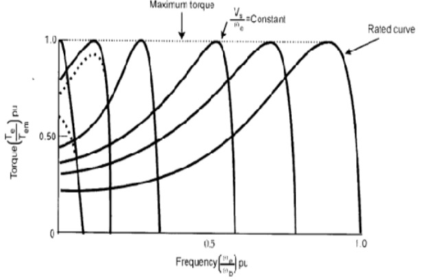
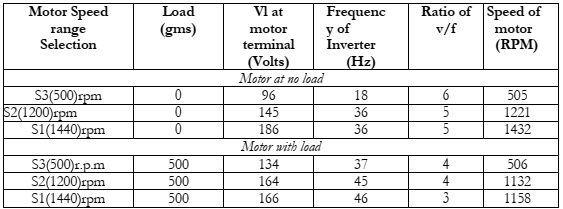
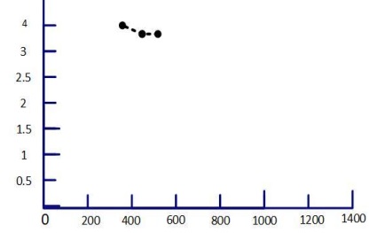
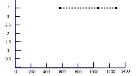
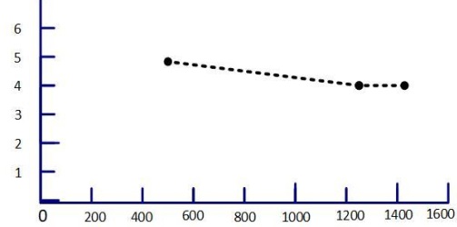
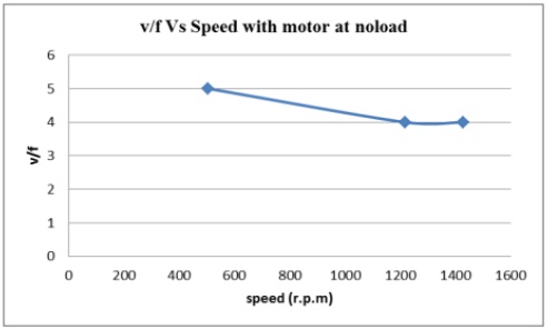
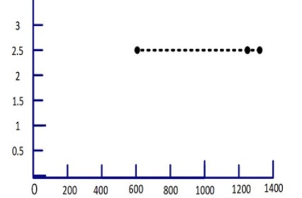
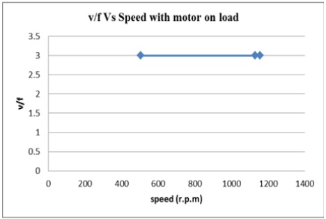
Induction motors operate at rated speed with no load when they are connected directly to the supply. When a motor is loaded, its speed begins to decline. As a result, the v/f approach is utilized to constantly operate the motor at less than maximum speed, both with and without 
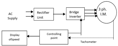
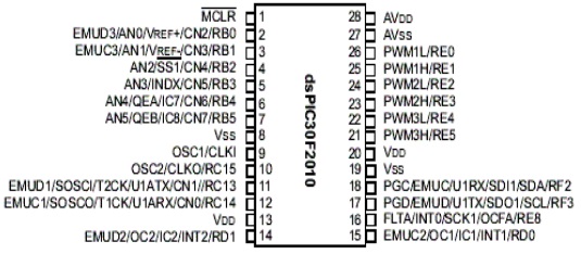
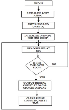
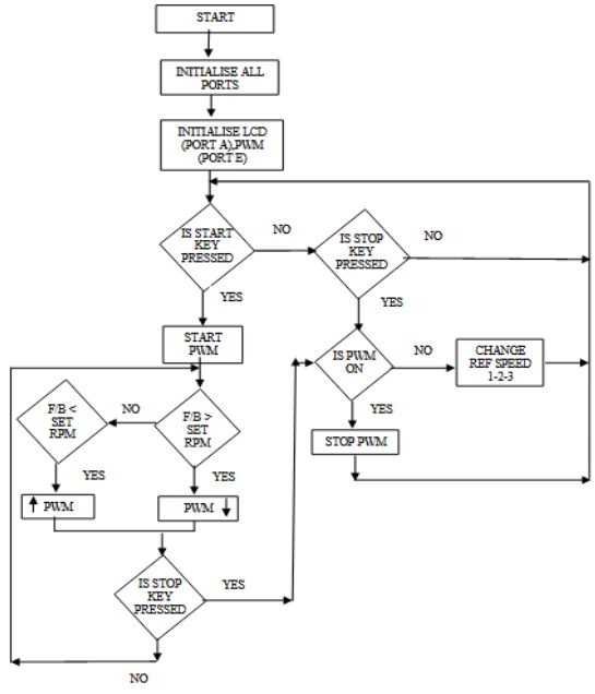
load. The PIC microcontroller is used to generate the PWM waveform and analyze the motor speed. The research includes two algorithms: one that monitors motor speed and the other that generates error signals based on stated and real-world speeds and modifies the frequency 
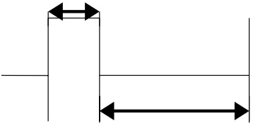
(f) and the voltage (v) of the PWM waveform.

Recommendation

If the v/f ratio is kept constant, a motor will operate at variable speed both with and without a load.

Reference

[1] Richardson MT, Patterson V, Parchment A. Microcontroller based space vector pulse width modulation speed control of three-phase induction motor. InSoutheastCon 2021 2021 Mar 10 (pp. 1-6). IEEE.

[2] Bayındır AB, Shraida A, Bayhan S, Abu-Rub H. Design and Implementation of Microcontroller Based Three Phase Induction Motor Experimental Set. In2022 10th International Conference on Smart Grid (icSmartGrid) 2022 Jun 27 (pp. 111-117). IEEE.

[3] Shyamkul SR, Jambhulkar DB, Indurkar V, Shinde M, Tiple N, Isasare M. SPEED CONTROL OF 1-Φ INDUCTION MOTOR DRIVE USING SCALAR METHOD: V/F CONTROL.

[4] Selvaperumal S, Krishnamoorthy N, Prabhakar G. A novel source side power quality improved soft starting of three-phase induction motor using a symmetrical angle controller through pic microcontroller. Bulletin of the Polish Academy of Sciences: Technical Sciences. 2021.

[5] Kannan R, Jenitha V, Karthikeyan K, Kumar AR. Speed control of three phase induction motor using Arduino and V/F technique. NVEO-NATURAL VOLATILES & ESSENTIAL OILS Journal| NVEO. 2021 Nov 7:1602-11.

[6] Waleed U, Waseem M, Shaukat H, Ijaz A, Almalaq A, Mohamed MA. An efficient FPGA based scalar V/f control mechanism of three phase induction motor for electric vehicles. In2021 31st Australasian Universities Power Engineering Conference (AUPEC) 2021 Sep 26 (pp. 1-6). IEEE.

[7] Erbakanov L. Implementation of Simplified Method for Constant V/F Speed Control of 3-phase Induction Motor. In2022 22nd International Symposium on Electrical Apparatus and Technologies (SIELA) 2022 Jun 1 (pp. 1-4). IEEE.

[8] Awdaa MA, Obed AA, Yaqoob SJ. A Comparative Study between V/F and IFOC Control for Three-Phase Induction Motor Drives. InIOP Conference Series: Materials Science and Engineering 2021 Jun 1 (Vol. 1105, No. 1, p. 012006). IOP Publishing.

[9] Gomes RR, Pugliese LF, Silva WW, Sousa CV, Rezende GM, Rodor FF. Speed Control with Indirect Field Orientation for Low Power Three-Phase Induction Machine with Squirrel Cage Rotor. Machines. 2021 Nov 27;9(12):320.

[10] Nikpayam M, Ghanbari M, Esmaeli A, Jannati M. Vector Control Methods for Star-Connected Three-Phase Induction Motor Drives Under the Open-Phase Failure. Journal of Operation and Automation in Power Engineering. 2022 Aug 1;10(2):155-64.

[11] Boros RR, Bodnár I. Grid and PV Fed Uninterruptible Induction Motor Drive Implementation and Measurements. Energies. 2022 Jan 19;15(3):708.

[12] Ahmed A, Shaikh AM, Shaikh MF, Shaikh SA, Soomro JB. Experimental study of various parameters during speed control of three-phase induction motor using GPIC and LabVIEW. Annals of emerging technologies in computing (AETiC). 2021 Jan 1;5(1):51-62.

[13] Vidlak M, Makys P, Gorel L. A Novel Constant Power Factor Loop for Stable V/f Control of PMSM in Comparison against Sensorless FOC with Luenberger-Type Back-EMF Observer Verified by Experiments. Applied Sciences. 2022 Sep 13;12(18):9179.

[14] Ramu SK, Irudayaraj GC, Devarajan G, Indragandhi V, Subramaniyaswamy V, Sam Alaric J. Diagnosis of Broken Bars in V/F Control Induction Motor Drive Using Wavelets and EEV Estimation for Electric Vehicle Applications. International Transactions on Electrical Energy Systems. 2022 Sep 5;2022.

[15] Angadi S, Yargatti UR, Suresh Y, Raju AB. Speed sensorless maximum power point tracking technique for SEIG-based wind energy conversion system feeding induction motor pump. Electrical Engineering. 2022 Mar 8:1-4.

[16] Hmidet A, Boubaker O. Real-time low-cost speed monitoring and control of three-phase induction motor via a voltage/frequency control approach. Mathematical Problems in Engineering. 2020 Apr 22;2020.

[17] Harsha AR, Pranupa S, Kumar BK, Rao SN, Indira MS. Arduino based V/f Drive for a Three Phase Induction Motor using Single Phase Supply. In2020 International Conference on Smart Technologies in Computing, Electrical and Electronics (ICSTCEE) 2020 Oct 9 (pp. 90-94). IEEE.

[18] Kıvrak S, Özer T, Oğuz Y. Design and implementation of dspic33fj32mc204 microcontroller–based asynchronous motor voltage/frequency speed control circuit for the ventilation systems of vehicles. Measurement and Control. 2019 Sep;52(7-8):1039-47.

[19] Santhiya K, Devimuppudathi M, Kumar DS, Renold AJ. Real time speed control of three phase induction motor by using lab view with fuzzy logic. Journal on Science Engineering and Technology. 2018;5(2):21-7.

[20] Pavithra G, Rao VV. Remote monitoring and control of VFD fed three phase induction motor with PLC and LabVIEW software. In2018 2nd International Conference on I-SMAC (IoT in Social, Mobile, Analytics and Cloud)(I-SMAC) I-SMAC (IoT in Social, Mobile, Analytics and Cloud)(I-SMAC), 2018 2nd International Conference on 2018 Aug 30 (pp. 329-335). IEEE.

[21] Quang NH. Speed Control of Induction Motor on C2000 DSP Platform. Review of Information Engineering and Applications. 2019 Dec 11;6(2):29-36.

[22] Athul AG, Banerji SC. Speed Control of Three Phase Squirrel Cage Induction Motor.

[23] Kumar SM. Nine-Switch Converter Fed Induction Motor with V/F Control using PIC Microcontroller.

[24] Mahato B, Jana KC, Thakura PR. Constant V/f control and frequency control of isolated winding induction motor using nine-level three-phase inverter. Iranian Journal of Science and Technology, Transactions of Electrical Engineering. 2019 Mar;43(1):123-35.

[25] Reddy Sudharshana K, Muralidhara V, Ramachandran A, Srinivasan R. Simulation and Experimental Validation of Common Mode Voltage in Three Phase Induction Motor Driven by Five Level Inverter Using PIC Microcontroller.

[26] Jithin J, Devika KR, Jasim Ali M, Murali K. Speed and Torque Control of 3 Phase Induction Motors using Periferal Interface Controller. International Journal of Research Studies in Electrical and Electronics Engineering (IJRSEEE) Volume. 2019;5:1-4.

[27] Kafle B, Basnet P, Ghimire A, Lamichhane A. Speed Control of a Single Phase Induction Motor using the V/f Method. In2019 Innovations in Power and Advanced Computing Technologies (i-PACT) 2019 Mar 22 (Vol. 1, pp. 1-4). IEEE.

[28] Tayebi A, Brahami M, Yaichi M, Boutadara A. Low complexity SVM technique of control implementation by microcontroller for three phase solar inverter. Environmental Progress & Sustainable Energy. 2019 Nov;38(6):e13271.

[29] Epemu AM, Enalume KO. Speed control of a single phase induction motor using step-down cycloconverter. International Journal of Industrial and Manufacturing Systems Engineering. 2018 May 15;3(1):6.

[30] Tri DC. Design of Driver Circuit to Control Induction Motor Applied in Electric Motorcycles. In2020 5th International Conference on Green Technology and Sustainable Development (GTSD) 2020 Nov 27 (pp. 326-333). IEEE.

[31] Hota A, Qasim M, Kirtley JL, Agarwal V. A novel three-phase induction motor drive for domestic fan application with improved reliability. In2018 IEEE International Conference on Power Electronics, Drives and Energy Systems (PEDES) 2018 Dec 18 (pp. 1-5). IEEE.

[32] Stefanov G, Cekerovski T, CitkusevaDimitrovska B, Stefanova S. 3-phase motor speed regulator based on microcontroller and intelligent power driver controller.

[33] Badmus EO, Wakeel RB. Wireless Speed Control for Induction Motor. American International Journal of Sciences and Engineering Research. 2020;3(1):33-42.

[34] Tayebi A, Brahami M, Yaichi M, Abdelkader B. Design and Implementation of SVM for Three Phase Inverter Fed an Induction Motor for Photovoltaic Stand-alone Pumping System. In2019 7th International Renewable and Sustainable Energy Conference (IRSEC) 2019 Nov 27 (pp. 1-6). IEEE.

[35] Kyslan K, Lacko M, Ferková Ž, Záskalický P. V/f control of five phase induction machine implemented on DSP using Simulink Coder. In2020 ELEKTRO 2020 May 25 (pp. 1-6). IEEE.

[36] Kesler S. Performance analysis of different PWM techniques on V/f-based speed control with adjustable boost voltage application for induction motors. PamukkaleÜniversitesiMühendislikBilimleriDergisi. 2018 Jan 1;24(5):797-808.

[37] VR RV, SELVI K. DESIGN AND IMPLEMENTATION OF ARM CORTEX-M4 PROCESSOR BASED CLOSED LOOP CONTROL OF THREE PHASE INDUCTION MOTOR. Journal of Electrical Engineering. 2018 May 24;18(4):12-.

[38] Jeyashanthi J, Santhi M. Performance of direct torque controlled induction motor drive by fuzzy logic controller. Journal of Control Engineering and Applied Informatics. 2020 Mar 26;22(1):63-71.

[39] Abdullah M, Naqvi AH. Techno-economic Study for Water Pumping by Solar Power Driven Three Phase Induction Motor. Sir Syed University Research Journal of Engineering & Technology. 2019 Jun 24;9(1).

[40] KULKARNI M, Renu B, Tejashree P, Komal S, Vaishali P. Speed Control of Universal Motor Using Sniversal Bridge. International Journal Of Innovations In Engineering Research and Technology [IJIERT] ISSN.:2394-3696.

[41] KULKARNI M, Renu B, Tejashree P, Komal S, Vaishali P. Speed Control of Universal Motor Using Sniversal Bridge. International Journal Of Innovations In Engineering Research and Technology [IJIERT] ISSN.:2394-3696.

[42] Syed S, Injam PK, Silvacus K. Parameter Unit Mode and External Mode Based Speed Control of Three Phase Induction Motor Using Variable Frequency Drive. In2020 International Conference on Renewable Energy Integration into Smart Grids: A Multidisciplinary Approach to Technology Modelling and Simulation (ICREISG) 2020 Feb 14 (pp. 99-104). IEEE.

[43] Thu MM, Naing TL. α-β Reference Frame Modeling and Implementation of VVVF Three-phase Inverter for Induction Motor Drive.

[44] Brindha B, Porselvi T, Ilayaraja R. Speed control of single and three phase induction motor using full bridge cycloconverter. In2018 International Conference on Power, Energy, Control and Transmission Systems (ICPECTS) 2018 Feb 22 (pp. 318-327). IEEE.

[45] Dida AH, Bourahla M, Ertan HB. Highly efficient Multi-Junction Solar Cells Performance Improvement for AC Induction Motor Control Using the dsPIC30F Microcontroller. In2019 International Aegean Conference on Electrical Machines and Power Electronics (ACEMP) & 2019 International Conference on Optimization of Electrical and Electronic Equipment (OPTIM) 2019 Aug 27 (pp. 211-215). IEEE.

[46] Samudera SH, Rifadil MM, Ferdiansyah I, Nugraha SD, Qudsi OA, Purwanto E. Three Phase Induction Motor Dynamic Speed Regulation using IP Controller. In2020 3rd International Seminar on Research of Information Technology and Intelligent Systems (ISRITI) 2020 Dec 10 (pp. 406-411). IEEE.

[47] Kumar K, Sharma LN, Naggarwal A, Sharma H, Mahato M, Kaur H. Designing of Thyristor Based Cycloconverter To Control Induction Motor. vol.;6:29-32.

[48] Anjum F, Sharma N. Speed Control of Induction Motor using Hybrid PID Fuzzy Controller. International Research Journal of Engineering and Technology (IRJET). 2018;5(11):576-80.

[49] Anjum F, Sharma N. Speed Control of Induction Motor using Hybrid PID Fuzzy Controller. International Research Journal of Engineering and Technology (IRJET). 2018;5(11):576-80.

[50] Bharathi PK, VinuPrakash UK. Labview Based Speed Control of Single Phase Induction Motor by V/F Control Method.