E-ISSN:2709-6130
P-ISSN:2618-1630

Research Article

International Journal of Innovations in Science & Technology

2024 Volume 6 Number 1 Jan-Mar

Optimizing UAV Wing Performance: A Computational Analysis with Computer-Based Algorithms for Composite Material Integration

Ullah. A, Ahmed. M. N, Saeed. B

Department of Mechanical Engineering, Air University Islamabad

Abstract

Introduction/Importance of Study: The aircraft wing, a vital component, demands intricate design to balance lift generation, drag reduction, and weight minimization. In advanced UAVs (Unmanned Aerial Vehicles), prioritizing stealth and low weight, a pioneering solution involves replacing traditional metallic wing components with composite materials, offering superior lightweight properties, strength, durability, and flexibility.

Novelty Statement: Since most of the studies focus on fuselage, wing ribs, and skin, this research emphasizes spars which are a primary component of the wing.

Material and Method: Composite material T800S/3900-2 is a widely used carbon fiber material in the aerospace industry, which is proposed to be utilized in wing spars. The finite element method is used to carry out the investigation and verification of this transition of materials from metals to composite materials.

Result and Discussion: By varying ply orientations and thicknesses of composite materials to match the stiffness and strength of metal spars, our findings demonstrate that composite wing spars exhibit equivalent stiffness, greater strength, and reduced weight compared to traditional metallic counterparts.

Concluding Remarks: The shift to composite materials in UAV wing design offers a transformative solution. This research shows that for optimal structural performance and achieving lower weight objective composite materials, composite materials are the most suitable materials for UAV wing spars.


Keywords: UAV wing; Composite materials; FEM; Lightweight; Structural Analysis.

Corresponding Author How to Cite this Article
Ahmad Ullah, Department of Mechanical Engineering, Air University Islamabad
Ahmad Ullah, Malik Nazir Ahmed, Babar Saeed, Optimizing UAV Wing Performance: A Computational Analysis with Computer-Based Algorithms for Composite Material Integration. IJIST. 2024 ;6(1):287-300 https://journal.50sea.com/index.php/IJIST/article/view/713

Introduction

In the realm of aviation, the use of Unmanned Aerial Vehicles (UAVs) has witnessed a notable surge in recent years, primarily attributed to their versatility, efficiency, and high-performance capabilities that ensure safer operations. The current research is focused on the optimization and integration of new materials in the UAVs to achieve the desired results. A historical analysis of aircraft materials shows a shift from early natural composites to metals, driven by challenges such as weak mechanical properties for higher load requirements. However, the advancements in composite materials and challenges in metal materials have created a new shift. Metals, despite their robustness, are burdened with high weights and necessitate regular maintenance. On the contrary, composite materials have low densities and improved mechanical properties in the desired direction which make them the best candidate for the aviation industry. Prominent aviation industries like the Boeing 787 and Airbus A350 use composite parts in their aircraft, marking a pivotal change attributed to the improved performance with lower weight and environmentally friendly characteristics. The use of composite material at a large scale not only reduces operational costs significantly but also decreases manufacturing expenses [1][2][3].

The research highlights the suitability of composite materials for UAV wing design, attributing their high stiffness-to-weight ratio, strength, durability, and flexibility to creating stronger and lighter structures in UAVs. Using composite materials in UAVs increases fuel efficiency and flight range [4][5]. Moreover, composite materials can absorb or scatter radar waves, reducing the radar signature of UAVs. Therefore, composites are used to improve the stealth capabilities of UAVs [6][7]. Finite Element Method (FEM) in modern engineering calculations plays an important role in solving complex engineering problems and optimization of structures. By dividing large domains into smaller finite elements and calculating approximate solutions at these elements, FEM provides quicker solutions and addresses geometric details that are challenging for analytical methods. The user emphasizes that the Finite Element Method (FEM) is the optimal choice for enhancing and optimizing various airplane parts due to its ability to handle complex geometric details that are not feasible to calculate using analytical methods. This tool is a reliable source while dealing with complex challenges in modern aerospace industries [8][9].

The increasing importance and demand of composite materials in aeronautics and automotive industries addresses challenges like cost reduction and material selection. The FEM has a wide range of solving models that encompass simulations of solids, plates, welds, and standard sections, catering to complex structural analyses at various scales. The FEM takes the failure criteria as a basis and gives optimal solutions for complex structures that is why it is considered an important calculation tool in the aerospace field for redesigning aircraft components covers covering all properties, failure criteria, and simulation elements such as solids, plate, and weld elements. This comprehensive approach proves its accuracy in providing static deformation in aircraft wings by simplifying complex geometries and aiding assessment in mechanical design aspects, making it an accurate tool for calculations of different components of composite materials, highlighting its reliability in providing engineering insights into static deformations and stiffness behavior of aircraft wings. These findings collectively show the important role of composite materials and the FEM in advancing aerospace and automotive engineering [10][11].

In the continuous struggle to reduce loads on primary flight components demands the structural design optimization of UAV wings. This optimization revolves around the use of the FEM which simulates and analyzes the complex structural behaviors. The primary aim of reducing the weight of UAV wings is a key parameter in increasing the overall performance and endurance of the aircraft. Researchers use advanced techniques and methodologies to design wings that not only withstand the static load but also demonstrate resilience in bearing the dynamic forces encountered during the flight [12][13].

In the dynamic landscape of the UAV industry, extending flight time emerges as a key concern. This motivates the researchers for optimal wing design to tackle challenges effectively. This iterative and complex journey includes a thorough comparison of diverse wing types and seeking the most suitable wing configuration tailored to specific mission requirements. The selection of an optimal wing design emerges as a pivotal factor by gaining considerable influence over flight efficiency and mission objectives. Structural analysis and optimization serve as the guiding compass in the quest to achieve prolonged flight times for UAVs [13][14]. In the field of aeroelasticity, researchers are exploring different ways to improve the wing structures of aerobatic aircraft. One notable approach is to replace the usual metal wings with layers of composite materials, blending strength with flexibility. Careful coordination of analytical and computational calculations is essential to thoroughly comprehend the effects of these structural changes. By adjusting the orientation of the fibers in the material, researchers have managed to increase flutter speeds. This achievement not only makes the aircraft safer but also increases its overall performance. This innovation and analysis is driving the evolution of aerobatic aircraft wing designs [15][16].

In the complex field of high-altitude, long-endurance Electrically-Powered Aerial Vehicle (EAV) wings, design takes center stage as a focal point. Researchers delve into the landscape of innovation by contemplating the substitution of conventional wing structures with cutting-edge composite materials. This strategic shift aims to minimize deflections and stress during flight, a crucial endeavor in extending the operational capabilities and endurance of EAVs. This metamorphosis in design proves indispensable, especially during prolonged airborne missions. This design evolution marks a significant advancement for high-altitude, long-endurance Electrically-Powered Aerial Vehicles [17][18]. The utilization of composite materials brings forth distinct advantages, notably the ability to manipulate lay-up orientations. This enables the attainment of isotropic properties through the creation of quasi-isotropic laminates. Additionally, symmetric lay-up sequences, like (± 45/0/90), provide flexibility in disregarding coupling terms. Quasi-homogeneous laminates, formed through these techniques, showcase consistent properties across bending, torsion, and extension, highlighting the versatility and tailored characteristics achievable with composite materials [19][20].

Laminates with identical lay-up orientations (e.g., (0°), (90°), and (45°)) are susceptible to rapid failure during bending, attributed to a weak fiber network. To augment the strain tolerance at failure points, laminates should incorporate at least three different plies. This strategic approach enhances structural robustness, addressing the limitations associated with rapid failure during bending in homogeneous lay-up configurations [21], Basri et al. (2019) present a layer-wise finite element model for static structural analysis of a CFRP laminated composite of a UAV wing. The above-mentioned study aims to identify the optimum design for a selected ply combination on a wing with a tubercle design at the leading edge [22]. Blended Wing Body (BWB) configurations have garnered notable attention owing to their aerodynamic efficiency, manufacturing simplicity, and enhanced fuel economy. In this regard, Sarmiento et al. (2022) delve into an exploration of the strength distribution within a semi-monocoque structure of a blended wing body UAV. Their study specifically focuses on a composite material based on pre-loaded jute fiber, aiming to unravel insights into the structural integrity and performance aspects of this innovative aircraft design [23].

In another comprehensive study, the investigation and comparison of Interlaminar Shear Strength (ILSS) and flexural properties encompass various laminate orientations (0°, 45°, (45°/-45°/45°)s, (±45°/0°/90°)s, and 90°) for unidirectional Carbon Fiber Reinforced Plastic (CFRP) and Glass Fiber Reinforced Plastic (GFRP) composites. The methodology involves subjecting double-notched specimens to tensile loads to measure ILSS. The application of Classical Laminate Theory (CLT) yields theoretical flexural properties, demonstrating good alignment with experimental results. Key findings indicate that 0° laminates exhibit higher flexural strength and stiffness, whereas (45°/-45°/45°) s laminates display heightened flexural strain compared to other orientations. The investigation further employs scanning electron microscopy to analyze fracture surfaces in both CFRP and GFRP composites across all laminate orientations, providing a comprehensive insight into the structural behavior of these materials [24].

Role of Computer Science:

The focus of this research is to improve UAV wing design by replacing metallic parts with composite materials. The FEM is used to check the feasibility of this transition of materials. The role of computer science plays a pivotal role in multiple aspects of this research. The FEA technique uses computer science-enabled algorithms to do a detailed examination of the structural integrity and performance of UAV wing spars. Computational modeling and simulation form the basis for designing and optimizing the wing structure virtually before the physical prototypes are constructed. These techniques are facilitated by principles of computer science. Computer-based algorithmic optimization checks various configurations of composite materials which are ply orientations and thicknesses to identify optimal combinations that meet stiffness, strength, and weight optimization criteria. Data analysis techniques handle the vast amounts of data generated during simulations and then extract valuable results. These results give insight into the performance of composite materials compared to traditional metallic parts. The graphical visualization tools aid in representing complex structural behaviors and making results comprehensible. Computer science accelerates automatic iteration of different parameters in the design while integrating with Computer-Aided Design (CAD) systems. This streamlines collaboration and enhances the overall efficiency of the design process. Computer science plays an integral role in the research by providing computational tools, algorithms, and methodologies. This enhances the understanding, design, and optimization of UAV wing spars to improve aircraft performance.

Flow of Research:

This study follows a systematic flow starting with CAD modeling of the UAV wing, followed by an estimation of the loads on the wing as shown in Figure 1. Subsequently, Finite Element Analysis (FEA) is conducted on the existing wing with metal spars and then subjected to post-processing to determine the actual stiffness of the wing. FEA is then performed on the wing with composite materials, using different stacking sequences to get the same stiffness of the wing.

Figure 1: Systematic Flow of Research.

Objective:

The primary objective of this study is to optimize UAV wing design by replacing traditional metallic components with composite materials, focusing on enhancing lightweight properties, strength, and stealth capabilities.

Novelty:

While many studies predominantly focus on fuselage and wing ribs and skin, this study specifically emphasizes wing spars. The carbon fibre-reinforced composites are used and different ply orientations are analyzed to get optimum results. Additionally, several other parts of the wing are included in the study to get a realistic overview of wing stiffness.

Material and Method

In this research, primarily two materials are used. Aluminum 2024-T3 and carbon-fiber composite material T800S/3900-2 Lamina. Table 1 illustrates the mechanical properties of Aluminum [25].

Table 1: Mechanical Properties of Aluminum 2024-T-3

The mechanical properties of unidirectional carbon fiber composite material T800S/3900-2 are listed in the following Table 2 [26].

Table 2: T800S/3900-2 Lamina Properties

Finite Element Method:

The FEM is a key numerical technique extensively used in structural engineering for the analysis of complex structures. It aids in understanding the physical behavior of the structure and also identifies the critical areas within the structure. By dividing complex geometries into smaller interconnected elements, FEM approximates the material's mechanical response. These elements are interconnected at nodes to form a mesh and mathematical models rooted in elasticity theory, representing structural behavior within each element. The results help to understand deformation patterns which makes it a powerful tool in structural engineering problems [27].

This study focuses on the wing design of a Medium Altitude and Long Endurance (MALE) UAV, The weight of the UAV is 5300 kg with a wing span of 152000 mm. The chord length at the root is 625 mm, tapering to 385 mm at the tip. The investigation includes thorough modeling of the entire wing, incorporating components such as skin, stringers, ribs, and spars. Initially, all components were assigned aluminum material in the first FEM model, establishing a reference for wing deflections. In the second FEM model, carbon-fiber reinforced composite material was assigned to the spars, with adjustments made to fiber orientations and layup thickness through an iterative process to achieve equivalent stiffness. Detailed information regarding the FEM models can be found in the following sections.

CAD Model:

The geometry of the wing is shown in Figure 2, which consists of different components such as skin, spars, ribs, stringers and a lug attachment with holes for rivets. Within the FEM model, the rivets are represented as beam elements with pre-tension applied.

Figure 2: UAV Wing geometry

Figure 3: Mesh details of wing

Mesh generation is a critical aspect of finite element analysis since the quality of the mesh directly influences the accuracy of the results. Parameters like stress and strain are computed at integration points within the elements and then extrapolated to the nodes. To ensure precision in computational loads and domains, a mesh convergence study was conducted. The mesh has a consistent 5mm size across the entire wing geometry [28]. The mesh of the wing is shown in the figure 4. Plate elements (mostly QUAD 4) are used for FEM model 1, while laminate elements are used in the second model.

Material Properties:

The materials and thickness of different parts are given in the following table.

Table 3: Material and part thickness of the first FEM model

Modeling of Composite Layers:

Creating composite layups in Femap, utilizing the Nx-Nastran Solver involves strategically various combinations and configurations. This approach aims to attain a stiffness level similar to that of the original model while reducing its total weight. To achieve this, the Classical Laminate Theory (CLT) serves as the foundation for designing the layup and determining the stacking sequence. Armed with the principles of CLT, one can effectively predict the structural response with consideration for both stacking sequence and boundary conditions [29].

Symmetric layups are employed to nullify the influence of the matrix [B], thus decoupling bending and extension, which enables a more straightforward and simplified solution to be pursued. Unidirectional plies demonstrate greater resistance to tension or compression, whereas angled plies excel in resisting torsion or twisting forces. For structures experiencing combined bending and twisting loads, plies positioned at various angles are essential [30][31][32]. Using the knowledge from the above literature the following stacking sequences are selected for comparison.

Table 4: Different sequences for ply orientation

Boundary Conditions:

The rigid elements were incorporated at the pinned connection locations of the lug attachments, with the middle nodes fixed [Ux=Uy=Uz=0, Rx=Ry=Rz=0].

The total lift force required for a single wing is WL = 25885 N

The total area of wing A = 11.192 m2

The lift pressure is calculated as P = WL/A = 0.00231 MPa

The general pressure distribution on the wing is shown in Figure 3.

Figure 4: Pressure profile around an aerofoil [33]

To achieve a similar pressure distribution effect, 65% pressure is applied at the front side, while 35% pressure is applied at the backside of the wing.

Front side pressure Pf = 0.65*P = 0.0015 MPa

Back side pressure Pb = 0.35*P = 0.00081 MPa

Strength Criteria:

Von Mises criterion is applied to metallic parts while for composite materials, the Hoffman’s criterion is used. The failure index for Hoffman’s theory is calculated using the following formula

S is allowable stress in shear

Xt allowable tensile stress in direction 1

Xc allowable compressive stress in direction 1

Yt allowable tensile stress in direction 2

Yc allowable compressive stress in direction 2

Result and Discussion

This section presents the results of the finite element analysis. It examines the structural integrity of the spars when constructed from various materials and evaluates their performance against different failure criteria. Additionally, it compares the overall deformation of spars made from aluminium with those constructed from composite materials to assess their relative stiffness. Furthermore, it compares weight optimization results for various combinations of ply orientation and thickness.

FE model 1 (All Parts are of Aluminum Material):

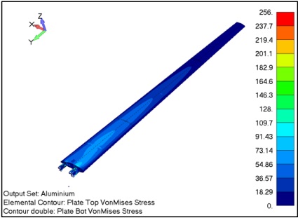
In this section, the findings from FE model 1 are presented, which consists of aluminum components and serves as the reference model. The model has been precisely manufactured and is currently in operational use. The safety factor for the Von Mises stress is 1.5, resulting in an allowable stress of 385/1.5 = 256 MPa. The maximum occurring stress is below this level. The following figures show the FEM results of model 1. Figure 5 shows the Von Mises stresses in the wing. The stresses are higher near the root area due to the maximum bending moment, while they are lower near the tip where the bending moment decreases. The maximum occurring stresses are below the allowable criteria.

Figure 5: Von Mises stress in the wing (FE Model 1)

Figure 6: Von Mises stress in the wing (FE Model 1)

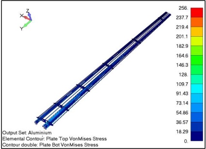
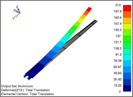
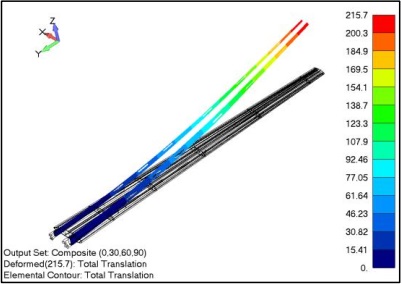
Figure 6 illustrates the Von Mises stresses in the wing spars. The maximum stresses are observed near the wing root. Since the front spars are stiffer than the back ones, they experience higher stress. However, it is important to note that the highest stress in the wing spars is lower than the allowable limit. In Figure 7, the total deformation of the wing is shown to be 213mm. This deformation is considered a reference for the composite spars. It is worth noting that the deformation near the root is minimal because the wing has more stiffness near the root area. The highest deflection occurs at the wing tip due to the flexibility of the tip.

Figure 7: Total deformation of the wing (FE Model 1)

Figure 8: Total deformation of the wing (FE Model 1)

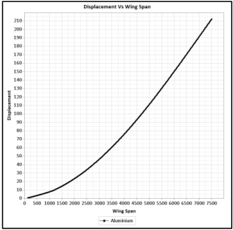
Figure 8 shows the displacement of the wing along the length of the wing. The graph illustrates the variation in deformation from the root to the tip of the wing. The deformation is not linear along the wing span because the stiffness of the wing varies along the length of the wing.

FE model 2 (Spars has Composite Material Sequence 1):

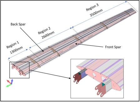
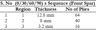
In this section, we present the findings from Finite Element (FE) Model 2, which incorporates spars made of composite materials with a layup sequence of [0/30/60/90] s degrees. Different thicknesses are assigned to different regions, for continuous distribution of material for front and back spars. The regions are highlighted in Figure 2.

Table 5: Material distribution for front spar

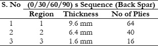
Table 6 shows the material distribution for the back spar.

Table 6: Material distribution for back spar

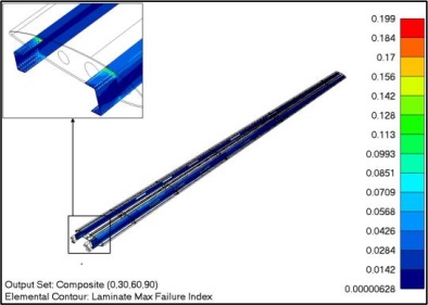
FEM model 2 exhibits an equivalent stiffness to FEM model 1. The maximum laminate failure index, at 0.199, demonstrates that with this specific arrangement and quantity of plies, the structural integrity of the spars is deemed satisfactory. Figure 9 shows the results of the maximum laminate failure index for FE model 2. The high index occurs near the root area. The index shows that spars with this sequence are strong enough to withstand the loads.

Figure 9: Maximum laminate failure index

Figure 10: Total deformation of spars

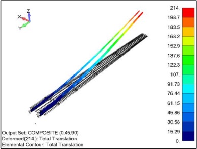
Figure 10 shows the deformations of spars in the FE model 2. The deformation at the wing tip corresponds to the deformation of metallic spars in the FE model 1. The wing stiffness behavior of the composite spars matches the results of metallic spars.

FE model 3 (Spars have Composite Material Sequence 2):

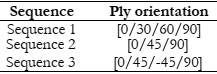
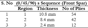
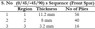
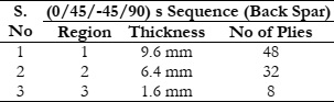
In this portion, we present the results obtained from Finite Element (FE) Model 3, which integrates spars constructed from composite materials following a layup sequence of [0/45/90] degrees. The material distribution for the front spar in FE model 2 is given in table 7.

Table 7: Material distribution for front spar

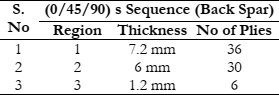
The Table 8 shows the material distribution for the back spar.

Table 8: Material distribution for back spar

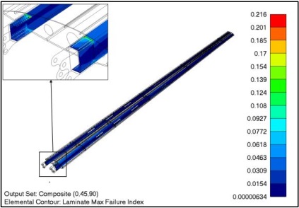
Figure 11 and Figure 12 show the results for Model 3. FEM model 3 demonstrates a stiffness comparable to that of FEM model 1. The maximum laminate failure index, at 0.216, indicates that with this particular arrangement and number of plies, the structural integrity of the spars is considered satisfactory.

Figure 11: Maximum laminate failure index

Figure 12: Total deformation of spars

Figure 12 illustrates deformations of spars in the FE model 3. The deformation at the wing tip corresponds to the metallic spars in the FE model 1. The wing stiffness behavior of the composite spars is consistent with the results of metallic spars.

FE Model 4 (Spars have Composite Material Sequence 3):

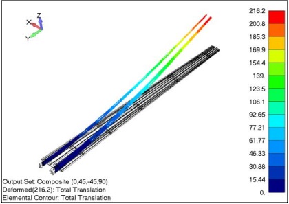
In this section, we present results from Finite Element Model 4, which utilizes composite material spars with a [0/45/-45/90] layup sequence. The material distribution for the front spar in FE model 3 is given in Table 9.

Table 9: Material distribution for front spar

Table 10 shows the material distribution for the back spar.

Table 10: Material distribution for back spar

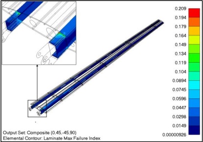
Figure 13 and Figure 14 show the FEM results for the model 4. The laminate failure index reaches a maximum value of 0.209, signifying that, given the specific configuration and ply count, the structural integrity of the spars is acceptable.

Figure 14 shows deformations of spars in the FE model 4. The deformation at the wing tip corresponds to the metallic spars in the FE model 1. The wing stiffness behavior of the composite spars is consistent with the results of metallic spars.

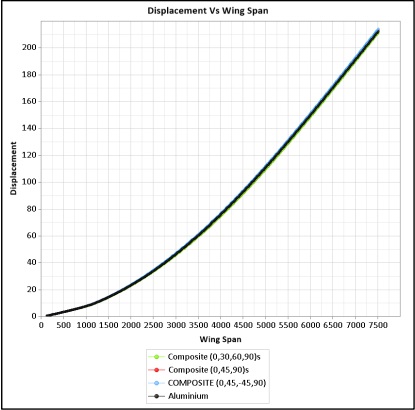
Figure 15 shows the deformations of the spars along the wing span in all FE models. The deformation of metallic spars and composite spars with different stacking sequences shows consistent behavior under the same loading. This illustrates that integrating composite material with specified stacking sequences will not change the stiffness of the behavior of the wing.

Figure 13: Maximum laminate failure index

Figure 14: Total deformation of spars

Figure 15: Total deformation of spars with all ply sequences

Discussion:

This section discusses the finite element analysis results, focusing on structural integrity and performance for spars made of different materials. Deformations, failure criteria, and relative stiffness are explored for aluminum and composite spars with different layup sequences across various FE models. Considering FE MODEL 1 (Aluminum Components), the aluminum model acts as a benchmark, showing real structural design with stresses distributed along the wing. Total wing deformation serves as a baseline for comparisons with subsequent composite spar models. FE MODEL 2 (Composite spars – sequence 1) introduces composite spars with a [0/30/60/90] layup sequence, showing equivalent stiffness to Model 1. The maximum laminate failure index confirms structural integrity, and deformation aligns consistently with metallic spars.

FE MODEL 3 (Composite spars – sequence 2), with a [0/45/90] layup sequence, shows comparable stiffness to Model 1. The maximum laminate failure index falls within limits, and deformation aligns consistently with metallic spars. FE MODEL 4 (Composite spars – sequence 3), using a [0/45/-45/90] layup sequence, shows equivalent stiffness to Model 1. Maximum laminate failure index and deformation analysis reinforce consistent behavior with metallic spars. The detailed overview shown in Figure 15 gives the comparison of deflections of the wing in all FE models. This study aimed to integrate composite materials without changing the stiffness. This is achieved by tailoring the thicknesses of the laminates of different stacking sequences. This iterative process is performed through computer science algorithms particularly Finite Element Analysis (FEA). This allows for a detailed examination of the strength and performance of UAV wing spars.

Computer-based algorithmic optimization plays a key role in finding optimal results by varying thicknesses and orientations of different plies of composite materials. This approach aims to achieve the best combinations meeting stiffness and strength criteria with reduced weight. The data science techniques made it possible to manage and analyze the data, providing important insights into how composite materials performance compared to traditional metal components.

Computer-aided design (CAD) systems coupled with FEM expedite the design process, leading to an efficient and iterative optimization process. The summarized results demonstrate that high strength and flexibility in UAV wings are attainable using composite materials. The well-optimized solution with reduced weight is a testament to the advanced FEM technique, with visual representations aiding in understanding the complex problem and achieving desired outcomes.

Conclusion

The primary objective of this study was to substitute aluminum with the composite material in spars while maintaining a similar physical behavior to metallic spars and achieving a reduction in overall weight. This transition in spar material was required to maintain the wing's stiffness at the same level, ensuring that the elastic behavior of the wing remained unaltered. To achieve this goal, Finite Element Method (FEM) analysis was employed, and various ply orientations were investigated to determine the most optimal combination. The following table presents a concise summary of the findings from this research.

Table 11: Summary of the research

The table 11 makes it evident that the optimal layup sequence is (0/45/90). This choice not only provides equivalent stiffness but also leads to a more significant reduction in weight.

Acknowledgement:

All authors contributed significantly with their valuable input to shape this manuscript. We are grateful for the collective commitment of all authors to the research presented here. All authors hereby acknowledge that this paper has not been previously published or submitted to other Journals.

Reference

[1] C. Soutis, “Aerospace engineering requirements in building with composites,” Polym. Compos. Aerosp. Ind., pp. 3–22, Jan. 2020, doi: 10.1016/B978-0-08-102679-3.00001-0.

[2] V. R. A. Prakash, M. Bourchak, H. Alshahrani, and K. A. Juhany, “Synthesis and characterization of lightweight unmanned aerial vehicle composite building material for defense application,” Biomass Convers. Biorefinery, pp. 1–12, Aug. 2023, doi: 10.1007/S13399-023-04736-2/METRICS.

[3] N. Mazlan, T. Chai Hua, S. M. Sapuan, and R. A. Ilyas, “Evolution of Aerospace Composite Materials,” Adv. Compos. Aerosp. Eng. Appl., pp. 367–385, Jan. 2022, doi: 10.1007/978-3-030-88192-4_18/COVER.

[4] M. Bhong et al., “Review of composite materials and applications,” Mater. Today Proc., Oct. 2023, doi: 10.1016/J.MATPR.2023.10.026.

[5] S. B. Nagaraju, H. C. Priya, Y. G. T. Girijappa, and M. Puttegowda, “Lightweight and sustainable materials for aerospace applications,” Light. Sustain. Compos. Mater. Prep. Prop. Appl., pp. 157–178, Jan. 2023, doi: 10.1016/B978-0-323-95189-0.00007-X.

[6] A. Marius, “General principles of passive radar signature reducing-stealth technology and its applications”, doi: 10.13111/2066-8201.2010.2.1.6.

[7] C. Xu et al., “Application of Carbon Composites in Unmanned Aerial Vehicles: A Review,” Lect. Notes Electr. Eng., vol. 861 LNEE, pp. 3479–3485, 2022, doi: 10.1007/978-981-16-9492-9_343/COVER.

[8] B. Szabó and I. Babuška, “Finite Element Analysis: Method, Verification and Validation, Second Edition,” Finite Elem. Anal. Method, Verif. Validation, Second Ed., pp. 1–363, Jan. 2021, doi: 10.1002/9781119426479.

[9] W. K. Liu, S. Li, and H. S. Park, “Eighty Years of the Finite Element Method: Birth, Evolution, and Future,” Arch. Comput. Methods Eng. 2022 296, vol. 29, no. 6, pp. 4431–4453, Jun. 2022, doi: 10.1007/S11831-022-09740-9.

[10] S. A. Ardila-Parra, C. M. Pappalardo, O. A. G. Estrada, and D. Guida, “Finite Element based Redesign and Optimization of Aircraft Structural Components using Composite Materials,” IAENG Int. J. Appl. Math., Dec. 2020, Accessed: Mar. 13, 2024. [Online]. Available: https://hal.science/hal-03020637

[11] S. D. Müzel, E. P. Bonhin, N. M. Guimarães, and E. S. Guidi, “Application of the Finite Element Method in the Analysis of Composite Materials: A Review,” Polym. 2020, Vol. 12, Page 818, vol. 12, no. 4, p. 818, Apr. 2020, doi: 10.3390/POLYM12040818.

[12] F. Mazhar and A. M. Khan, “Structural design of a UAV wing using finite element method,” Collect. Tech. Pap. - AIAA/ASME/ASCE/AHS/ASC Struct. Struct. Dyn. Mater. Conf., 2010, doi: 10.2514/6.2010-3099.

[13] K. Raja Sekar, M. Ramesh, R. Naveen, M. S. Prasath, and D. Vigneshmoorthy, “Aerodynamic design and structural optimization of a wing for an Unmanned Aerial Vehicle (UAV),” IOP Conf. Ser. Mater. Sci. Eng., vol. 764, no. 1, p. 012058, Feb. 2020, doi: 10.1088/1757-899X/764/1/012058.

[14] M. A. Khan et al., “A Study on Flight Time Enhancement of Unmanned Aerial Vehicles (UAVs) Using Supercapacitor-Based Hybrid Electric Propulsion System (HEPS),” Arab. J. Sci. Eng., vol. 46, no. 2, pp. 1179–1198, Feb. 2021, doi: 10.1007/S13369-020-04941-5/METRICS.

[15] S. Guo, “Aeroelastic optimization of an aerobatic aircraft wing structure,” Aerosp. Sci. Technol., vol. 11, no. 5, pp. 396–404, Jun. 2007, doi: 10.1016/J.AST.2007.01.003.

[16] N. Z. Zaki et al., “Effect of Skin and Spar Laminate Orientations on Flutter of Composite UAV Wing,” J. Aeronaut. Astronaut. Aviat., vol. 51, no. 2, pp. 201–211, Jun. 2019, doi: 10.6125/JOAAA.201906_51(2).05.

[17] K. K. Rumayshah, A. Prayoga, and M. Agoes Moelyadi, “Design of High Altitude Long Endurance UAV: Structural Analysis of Composite Wing using Finite Element Method,” J. Phys. Conf. Ser., vol. 1005, no. 1, p. 012025, Apr. 2018, doi: 10.1088/1742-6596/1005/1/012025.

[18] O. A. Adeleke, G. E. Abbe, P. O. Jemitola, and S. Thomas, “Design of the Wing of a Medium Altitude Long Endurance UAV,” Int. J. Eng. Manuf., vol. 12, no. 1, p. 37, Feb. 2022, doi: 10.5815/IJEM.2022.01.04.

[19] E. Valot and P. Vannucci, “Some exact solutions for fully orthotropic laminates,” Compos. Struct., vol. 69, no. 2, pp. 157–166, Jul. 2005, doi: 10.1016/J.COMPSTRUCT.2004.06.007.

[20] A. Vincenti, P. Vannucci, and G. Verchery, “Influence of orientation errors on quasi-homogeneity of composite laminates,” Compos. Sci. Technol., vol. 63, no. 5, pp. 739–749, Apr. 2003, doi: 10.1016/S0266-3538(02)00263-4.

[21] A. Puck and H. Schürmann, “Failure analysis of FRP laminates by means of physically based phenomenological models,” Fail. Criteria Fibre-Reinforced-Polymer Compos., pp. 832–876, Jan. 2004, doi: 10.1016/B978-008044475-8/50028-7.

[22] E. I. Basri et al., “Performance analysis of composite ply orientation in aeronautical application of unmanned aerial vehicle (UAV) NACA4415 wing,” J. Mater. Res. Technol., vol. 8, no. 5, pp. 3822–3834, Sep. 2019, doi: 10.1016/J.JMRT.2019.06.044.

[23] E. Sarmiento, C. Díaz-Campoverde, J. Rivera, C. Cruzatty, E. Cando, and E. Valencia, “Aero-structural numerical analysis of a blended wing body unmanned aerial vehicle using a jute-based composite material,” Mater. Today Proc., vol. 49, pp. 50–57, Jan. 2022, doi: 10.1016/J.MATPR.2021.07.470.

[24] K. Naresh, S. Krishnapillai, and V. Ramachandran, “Effect of Fiber Orientation on Carbon/Epoxy and Glass/Epoxy Composites Subjected to Shear and Bending,” Solid State Phenom., vol. 267, pp. 103–108, 2017, doi: 10.4028/WWW.SCIENTIFIC.NET/SSP.267.103.

[25] L. Ünlüsoy, “Structural design and analysis of the mission adaptive wings of an unmanned aerial vehicle,” 2010, Accessed: Mar. 13, 2024. [Online]. Available: https://open.metu.edu.tr/handle/11511/19160

[26] and J. H. C. S. Gi, D. Kumar, Y. Park, J.H. KweonJ.H, “Structural Design and Analysis of Composite Aircraft Fuselage Used to Develop AFP Technology,” 2013.

[27] G. R. Liu and S. S. Quek, “The Finite Element Method: A Practical Course: Second Edition,” Finite Elem. Method A Pract. Course Second Ed., pp. 1–433, 2013, doi: 10.1016/C2012-0-00779-X.

[28] G. Kanesan, S. Mansor, and A. Abdul-Latif, “Validation of UAV wing structural model for finite element analysis,” J. Teknol., vol. 71, no. 2, pp. 1–5, 2014, doi: 10.11113/JT.V71.3710.

[29] V. Giurgiutiu, “Structural health monitoring (SHM) of aerospace composites,” Polym. Compos. Aerosp. Ind., pp. 449–507, Jan. 2015, doi: 10.1016/B978-0-85709-523-7.00016-5.

[30] C. B. York, “On Bending-Twisting coupled laminates,” Compos. Struct., vol. 160, pp. 887–900, Jan. 2017, doi: 10.1016/J.COMPSTRUCT.2016.10.063.

[31] D. Cui and D. Li, “Bending-twisting coupled structures based on composite laminates with extension-shear coupling effect,” Compos. Struct., vol. 209, pp. 434–442, Feb. 2019, doi: 10.1016/J.COMPSTRUCT.2018.09.095.

[32] R. E. Murray, D. A. Doman, and M. J. Pegg, “Finite element modeling and effects of material uncertainties in a composite laminate with bend–twist coupling,” Compos. Struct., vol. 121, pp. 362–376, Mar. 2015, doi: 10.1016/J.COMPSTRUCT.2014.11.035.

[33] “How to read representations of pressure around an airfoil? - Aviation Stack Exchange.” Accessed: Mar. 13, 2024. [Online]. Available: https://aviation.stackexchange.com/questions/33450/how-to-read-representations-of-pressure-around-an-airfoil