E-ISSN:2709-6130
P-ISSN:2618-1630

Research Article

International Journal of Innovations in Science & Technology

2024 Volume 6 Number 1 Jan-Mar

Effect of Crack Location and Orientation on Crack Growth in Boiler Tube: Theoretical and Computational Investigation

Rahman. M, Saeed. B

Institute of Avionics and Aerospace, Air University, Islamabad, Pakistan

Abstract

Introduction/Importance of Study:

Safety is the paramount concern in the operations and inspections of pressure vessels, such as water tube boilers. Defects in the boiler tubes can lead to the development of cracks.

Novelty Statement:

The investigation focuses on the effect of crack location and orientation on crack growth under cyclic loading which has been analyzed computationally using Separate Morphing and Re-meshing Technology (SMART) in ANSYS. The effect of location on crack growth is primarily focused which is theoretically investigated as well using Simpson’s Integration of Paris’s Law.

Materials and Method:

The tube in focus is a component of a D-type water-tube industrial boiler, crafted from low-carbon steel (SA 178 A). For the effect of location, semi-elliptical cracks on inner and outer tube surfaces have been studied both theoretically and computationally.

Results and Discussion:

Theoretical investigation revealed that cracks on the inner tube surface exhibit a 30.28% higher accumulative growth rate compared to the outer surface, attributed to hoop stress distribution. For investigating the effect of orientation elliptical embedded cracks at certain orientations have been examined computationally and the critical plane orientation for crack growth is identified as perpendicular to the hoop stress.

Concluding Remarks:

In conclusion, the study underscores that cracks grow faster when located at the inner surface and oriented perpendicular to the hoop stress.


Keywords: Tubes; Fracture Mechanics; Weight Function; Stress Intensity Factor; Crack Growth; ANSYS SMART; Simpson’s Integration.

Corresponding Author How to Cite this Article
Majeed ur Rahman, Institute of Avionics and Aerospace, Air University, Islamabad, Pakistan
Majeed ur Rahman, Babar Saeed, Effect of Crack Location and Orientation on Crack Growth in Boiler Tube: Theoretical and Computational Investigation. IJIST. 2024 ;6(1):333-350 https://journal.50sea.com/index.php/IJIST/article/view/720

Introduction

Tubes in water boilers, serving as pressure vessels, are indispensable assets for industries, including power generation, process industries, and oil and gas. Operating under internal pressure, these vessels play a crucial role in safely containing fluids at high pressures within confined workplaces, where the well-being of human lives is at risk. Poor maintenance and design, and neglecting the safety protocols increase the probability of Boiling Liquid Expanding Vapor Explosion (BLEVE) [1] and leaks, resulting in structural damage, burns, and fatalities [2]. The reliable performance of these pressure vessels is essential for the smooth operation of industries that heavily depend on their functionality and safety standards [3][4][5].

Cracks in these tubes can stem from a variety of sources including microstructural imperfections, manufacturing, fabrication, and welding defects, and in-service corrosion, as evidenced by the fractographic analysis of D. Ghosh et al [6] and E. Febriyanti et al [7]. These defects can be detected using various Non-Destructive Techniques (NDT) [8] and idealized as semi-elliptical cracks [9]. In the realm of metals, artificial intelligence and deep learning methods such as semantic segmentation and object detection, are increasingly employed for surface defect detection [10]. Consequently, preventive measures are required to reduce the risk of potential tube failure, given its potential to profoundly impact overall industry performance. Post-failure analyses of boilers and tubes have been extensively undertaken [11][12][13][14][15] with findings consistently highlighting the association between failures and leaks and the formation of cracks, particularly along the axis of the tubes. Subsequently, it is crucial to consider the behavior of crack growth in early design and later for Fitness-For-Service (FFS) evaluation [9].

Under static loading conditions, pre-existing cracks can either remain stable or could grow catastrophically, leading to a leak or blast depending on the design criteria used [16]. The fate of the structure hinges upon the value of the Stress Intensity Factor (SIF) associated with a specific crack. If the SIF surpasses the critical stress intensity factor, rapid crack growth can occur, potentially resulting in calamitous failures due to high fluid pressures. Conversely, if the SIF value associated with a crack is smaller than the critical stress intensity factor, it could be confidently stated that the structure and crack are in harmony [17]. The critical SIF is a material property, and at specific loading conditions, the value of SIF is calculated and then compared with it. Under cyclic loadings, Stable crack growth takes place dictated by Paris’s law if the SIF is in the range of threshold and critical SIF values. Below the threshold, the SIF value crack does not grow. When SIF crosses the critical SIF the crack growth becomes unstable resulting in catastrophic failure [18].

For a flat plate with a through crack under uniform tensile loading, it is easy to analytically determine mode one, mode two, and mode three SIFs [19]. However, as the geometry of the structure and the loading nature vary, determining the SIFs becomes challenging. H. Yuan et al [20] used the NASGRO software suit and MATLAB’s regression analysis and developed an empirical model to find the SIF of an edge crack. AFGROW is used professionally for crack growth problems with high accuracy along with NASGRO [21]. Visual FORTRAN has been used to write the source codes for solving the SIF and crack growth problems and has been used by M. Alshoaibi to investigate non-planer multiple cracks and revealed that the crack tips with high SIFs have a higher tendency to coincide [22]. D. Angela comparatively studied cracks in compact test specimens analytically and computationally utilizing the ABACUS software suit [23]. T. Htut investigated a crack developed in a 2.03 mm thick tube using NASTRAN solvers [24]. These commercial software packages use extended finite element methods (XFEM), which involve re-meshing to achieve greater accuracy. However, this approach often results in denser meshes, leading to increased computational time compared to methods like SMART [22]. In another study, Niu et al [25][26] investigated central symmetric and asymmetric kinked cracks with different configurations. The study revealed that main crack length exerts a greater influence on SIF as compared to kinked length.

Coêlho et al [27] conducted a study on a hollow cylindrical tube containing a semi-elliptical crack and analyzed the corresponding SIF. SIF on the major and minor axes of a semi-elliptical crack has been determined by Ligoria et al [28] using the empirical relations of Voort et al [29]. For a semi-elliptical circumferential crack, the SIF has been studied by C. D. Wallbrink and A. Zareei [30][31]. However, relying solely on crack growth analysis in planes with high tensile stresses is not always conclusive. S. Melin [32] demonstrated analytically that crack growth is not consistently greater when perpendicular to the larger principal stress. The growth of microstructural cracks can be analyzed with Paris’s law [17] and can be linked to the sliding and opening dislocations which is shown by F. McDowell [33] who also discussed the limitation of crack growth of sub-granular size cracks using linear elastic fracture mechanics, where the crack growth rate fluctuates by encountering new grain boundaries. Based on the critical plane concept of A. Karolczuk [34], multi-axial fatigue failure criteria have also been reviewed by A. Moftakhar [35], calculating stress components at the tip of the notch with multi-axial loading. Similarly, the effect of crystal orientation over the SIF is studied by M. Kamaya [36]. M. Yaylaci simulated an edge and internal crack to estimate the SIF [37]. O. Elmhaia used a mesh-free approach to find out SIF at the tip of the crack, and this method was based on the Weighted Least Squares Method (WLSM) in combination with the visibility criterion and stresses extrapolation method [38]. Using cohesive zone methodology, P. K. Pati demonstrated that a universal shape is achieved after the growth of an initially small semi-elliptical flaw [39].

Objectives:

The primary objective of this study is to comparatively analyze the effect of location on crack growth both computationally and theoretically. To achieve this goal, a semi-elliptical crack is investigated at two key locations: the inner and outer surfaces of the tube. Additionally, the effect of orientation on crack growth is also studied computationally as shown in Figure 1. The critical plane orientation has been determined in which the elliptical crack has initially defined and grows faster along its x-axis of the crack coordinates leading to a leak across the wall thickness.

Figure 1: Location of SESC and Orientation of EEC

Novelty:

In this research, cutting-edge technology, namely Separate Morphing and Re-meshing Technology (SMART) by ANSYS within its Fracture Module, has been utilized for crack growth analysis. This advanced methodology allows for a detailed examination of crack propagation behavior in tubes, considering both surface and embedded cracks. The study encompasses both theoretical and computational analyses to investigate crack growth. Theoretical solutions for the crack growth of semi-elliptical surface cracks have been derived, complementing the computational results obtained through the SMART technology. The growth rates of semi-elliptical inner and outer surface cracks have been compared and the most critical crack location and orientation have been identified.

Material and Method

Tube of Industrial Water-Tube (IWT) boiler with D type configuration has been focused as it performs under internal pressure, unlike fire tube boilers. Moreover, it is widely used in many process industries for steam generation [40]. Material selection and determination of the wall thickness of a boiler tube are closely intervened processes. Two primary approaches are commonly utilized for this purpose [16] design by analysis and design by rules. Design by analysis involves selecting a material against which an optimized thickness is calculated for the pressure vessel. Materials are typically categorized based on safe pressure vessel design criteria, namely yield before fracture and leak before fracture. In the yield before fracture criterion, the pressure vessel wall undergoes yielding before catastrophic failure, allowing for the detection and implementation of safety measures. Whereas in leak before break criteria a through crack is formed in the PV wall and the fluid inside leaks, which could be detected easily before the catastrophic failure takes place. Carbon steels like SA 178 A are often recommended for applications where leak-before-break criteria are prioritized. These materials are commonly used in boiler tubes, as indicated in ASME BPVC.II.D Table 1A [41], and fall within the fracture before the yield zone [42]. From PG-27.2 of ASME BPVC section I [43] the wall thickness of the tube can be calculated by equation 1.

Where t is the thickness of the tube wall, P is the maximum allowable working pressure according to PG-21, D is the outer diameter of the cylinder, and S is the maximum allowable stress according to PG-23 which is 85 MPa at 375 C° according to ASME BPVC.II.D Table 1A [41] and e is the fabrication value which is zero in this case. For some carbon steels like SA-178 Grade A, SA-226, and SA-192 using the equation for wall thickness table PWT-10 has been developed in ASME BPVC section I [43]. These interdependent parameters are given in Table 1. The material constants C and m for Paris’s law for this carbon steel are assumed the same as for Martensitic Steel [44].

Table 1: Material Properties and Tube dimensions

Methodology:

The assessment of SIFs and subsequent crack growth primarily depend upon the stress state therefore FEA results of stresses have been validated using Lame’s equations. Tangential or hoop (σ_t), radial (σ_r), and longitudinal (σ_a) stresses are given in equations 2-4 [45] respectively where R_o and R_i are the external and internal radii respectively while P is the internal pressure, contours of these stresses have been produced using MATLAB function polercont [46].

For a semi-elliptical surface crack as shown in Figure 2a in a cube under uniform stress distribution equations 6 to 14 [17] are given where the SIF is determined using equation 6.

Figure 2: (a). Semi-Elliptical Crack [17]. (b). Crack Growth per Step.

In equation 7 λ_s is the surface correction factor for the semi-elliptical cracks and Q which is given by equation 8 depends on the ratio a/c, f(φ) in equation 9 depends upon the angle φ just like λ_s.

The SIF is used to solve 12-14 for the number of cycles ∆N and ∆c simultaneously for specific crack growth ∆a along the minor axis which are resulted from the Simpson’s integration of Paris’s Law as given in equation 10. The applied traction σ_yy is uniform at the remote boundaries.

Equation 12 must correspond to the minor axis and Equation 13 to the major axis for example in Equation 14 f_(90°) (a,c) means 〖∆K〗_(90°) is for the minor axis in this case. Equations 12 and 13 were solved iteratively for specific numbers of steps as Simpson’s method suggests. This method allows for numerical integration of multivariable problems such as semi-elliptic crack growth problems and is more accurate than its counterpart trapezoidal method. In this study, the crack growth has been solved in ANSYS and MATLAB with 10 steps. When it comes to pressure vessels like tubes the stresses such as hoop stress along the thickness are non-uniform as discussed earlier, in this case, the Taylor series of hoop stress was used to find the SIF given by equations 15 and 16 [17] for inner and outer surface semi-elliptical crack respectively.

The SIFs are given in terms of Influence Coefficients G_n, n is the degree of stress polynomial where n = 0,1,2,3,4. For each term of the polynomial, there exists a SIF. For each SIF there exists an influence coefficient. Using the principle of superposition the sum of these SIFs gives the overall SIF. Mode I SIF of a semi-elliptical crack in a tube [45] was determined analytically. The method employed utilizes weight functions [47][48] and universal weight function [49] being specifically employed to calculate Mode I SIF with Lame’s hoop stress distribution [17][45][50]. The second Glinka-Shen Universal Weight Function (GSUWF) [47] is used to determine the SIF for a semi-elliptical crack in a tube, yielding influence coefficients [51][52]. The second of Glikna-Shen Universal Weight Function given in equation 18 [47] has been substituted in equation 17 [17]. In contemporary engineering practices, the utilization of weight function methods remains crucial, particularly when dealing with non-uniform stress distributions such as hoop stresses in the tube walls.

This results in geometric coefficients M_ia and M_ic as given in equations 19-21 and 27-29 for minor and major axes respectively for i = 1,2,3. which are expressed in terms of two influence coefficients G_n with n = 0,1 [51], where A_j and B_j in equation 22-23 corresponds to the minor axis. Thus〖 G〗_2, G_3, and G_4 could be determined for the minor axis.

Similarly to find G_2, G_3 and G_4 Equations 32-34 for the major axis M_ic in equation 27-29 are given in terms of G_0 and G_1, which in turn are given in terms of C_j and D_j in equation 30-31 for major axis with j = 0,1,2,3 [53]. Once the value of SIF is known equation 12 and 13 can be used to investigate the crack growth as in Figure 3.

Figure 3: SESC with SIF and crack propagation on the minor and major axis which can leak the tube due to its internal pressure

Despite the advancement in computational power, reliance on software like ANSYS Static Structural is common, capable of determining SIF in all three modes for various structures and stress distributions [54]. It can analyze the stability or catastrophic failure of a crack based on applied tractions, providing SIF results throughout the crack tip. However, results were obtained only at the minor and the major axes of the semi-elliptic crack for comparison with analytical results because the results obtained analytically are only for the major and minor axes. Importantly, the tube material was assumed to be linearly elastic, and it has been established that peak stresses fall below yield stress, even during leakage. MATLAB was used to obtain the contours of Lame’s stresses, compared with ANSYS results. Additionally, Simpson’s integration is applied to a cubic specimen under uniform stress distribution to establish a baseline. Subsequently, SIFs have been analyzed for semi-elliptical inner and outer surface cracks in the tube, exploring crack growth dynamics in the tube to investigate the effect of crack location. To investigate the effect of crack orientation on crack growth and cycles to leak, different planes have been defined by taking a crack in a plane perpendicular to hoop stress as a reference plane Figure 4a. Upon rotation at certain angles, major orientations have been obtained, as shown in Figure 4.

Figure 4: Different Planes for embedded crack in the tube

Flow of Research:

In summary, crack growth has been primarily investigated within a tube structure, with an initial focus on determining the tube dimensions in accordance with the guidelines provided by the American Society of Mechanical Engineers Boiler and Pressure Vessels Codes (ASME BPVC). Theoretical and computational analyses have been employed to evaluate the three principal stresses (hoop, longitudinal, and radial stresses) within the tube. Two types of cracks have been specifically addressed: semi-elliptical surface cracks (SESC) and elliptical embedded cracks (EEC) located in the tube wall. The SIF and crack growth in SESC in tubes has been analyzed both theoretically and computationally. Meanwhile, the analysis of EEC within the tube has been exclusively carried out through computational simulations utilizing ANSYS. Furthermore, to establish a theoretical foundation, the crack growth of an SESC within a cube has also been examined, as depicted in Figure 5.

Figure 5: Flow of Research

Result and Discussion

Stresses in Tube:

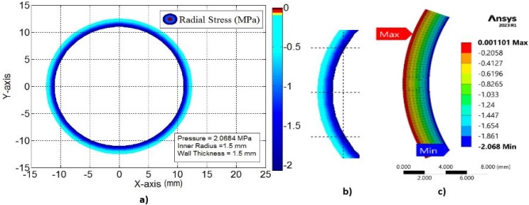
The tri-axial stress state has been analyzed both theoretically using Lame’s equations and computationally using ANSYS. Figure 6a and Figure 6b depicts the theoretical contours of hoop stress distribution obtained from Lam’s equations with the help of MATLAB whereas Figure 6c represents the computational results using ANSYS. Figure 6 is the testimony of the accurate computational results for hoop stress.

Figure 6: (a). Contours of Closed-form Solution of Hoop Stress. (b). Hoop Stress distribution through the thickness of the tube. (c). Hoop Stress (FEA)

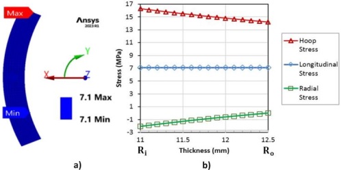
In the same fashion for radial stresses, Figure 7a and Figure 7b represents the theoretical results. While utilizing ANSYS Figure 7c depicts the computational results. Figure 8a shows the computational results of longitudinal stress. Figure 8b is the graphical representation of the Lame’s equations which is in scrutiny with the stress distributions in Figure 6 to Figure 8.

Figure 7: (a). Closed-form Solution of Radial Stress with Filled Contours. (b). Radial Stress Distribution through the Thickness of the Tube. (c). Radial Stress (FEA)

Figure 8: (a). Longitudinal Stress MPa (FEA). (b). Principle Stresses in Tube

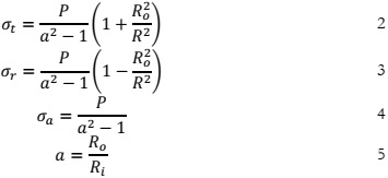
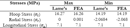
The stress analysis of the tube reveals that the maximum principle stress is the hoop stress which is higher at the inner surface of the tube. The radial stress is compressive while the longitudinal stress is uniform across the wall thickness. The comparison of maximum theoretical and computational stresses in the tube wall has been done in Table 2.

Table 2: Comparison of Maximum and Minimum Principle Stresses (MPa)

SIF and Crack Growth of Semi-Elliptic Crack in Uniform Stress Distribution:

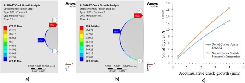
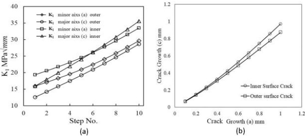
The growth of a semi-elliptical crack in a cube under uniform stress distribution had been analyzed with ten steps. The SIF in the first and last steps have been shown in Figure 9a and Figure 9b, in which the minimum value of SIF occurred at the minor axis which is the deepest point on the crack tip in the simple cubic structure, and the greater on the major axis. As the crack was grown the value of SIF increased as well.

Figure 9: (a). SIF in Step 1 of Analysis. (b). SIF in final step 10 of the analysis. (c). Crack Growth and No. of Cycles, Comparison of results from ANSYS SMART Crack Growth and Simpson’s Integration for an SESC in a Uniform Stress Distribution

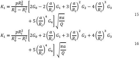
The comparison between crack growth results obtained from ANSYS SMART and MATLAB, depicted in Figure 9c, reveals notable discrepancies. MATLAB employs double 1/3 Simpson’s integration of Paris’s law as in equations 12 and 13 to calculate ∆c and the number of loading cycles, resulting in larger values compared to ANSYS SMART. This deviation could be reduced by increasing the number of steps in both analyses, contours at the crack tip, and the crack front elements in ANSYS.

SIF and Crack Growth of Semi-Elliptic Crack under Non-Uniform Stress Distribution:

Stress Intensity Factor:

Figure 10: (a). Wire Frame View of a Tube Part under observation with Tetrahedral Fracture Mesh with C3D10 type of elements. (b). SIF of the Semi Elliptical Crack on the inner surface. (c). Top view of the crack in the tube on the inner surface

Figure 11: (a). Definition and Positioning of the crack coordinates on the outer surface. (b). Crack Definition. (c). SIF, FEA results of the Semi Elliptical crack with top view

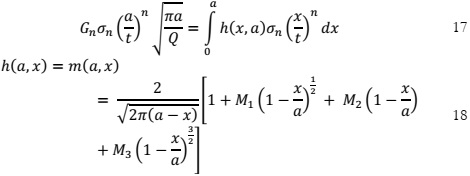
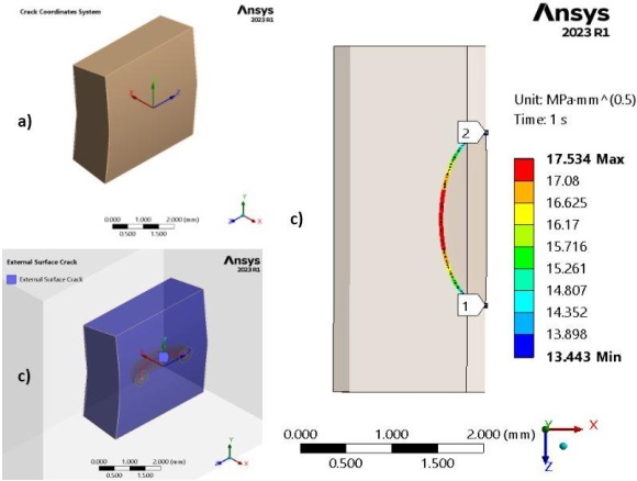
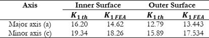
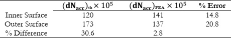
Figure 10 and Figure 11 show the SIF for the inner and outer surface semi-elliptical crack respectively, likewise the SIF was solved using equations 15 and 16 for the inner and outer surface. The FE results obtained are compared in Table 3.

Table 3: SIF (MPa) Results comparison, FEA and using the Influence Coefficients from Glinka-Shen Universal Weight Function Method (G-S UWFM)

Simpson’s Integration:

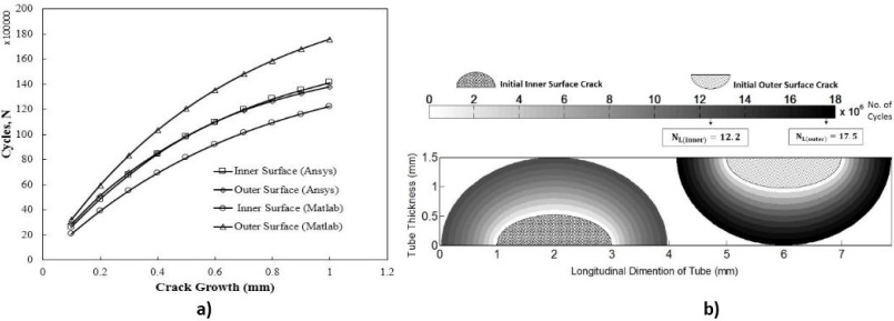
As for the stress ratio R = 0, ∆K = K-0, Which was estimated using equations 15 for the inner and 16 for the outer surface and plugged in equations 12 and 13 to find the number of cycles and crack growth along the major axis iteratively. The number of cycles for both inner and outer surface cracks using Simpson’s integration and ANSYS SMART are compared in Figure 12a. Using MATLAB for Simpson’s integration the number of cycles is lower for the inner and higher for the outer surface crack. Conversely, the results from ANSYS SMART are the same for cracks on inner and outer surfaces as shown in Figure 12b and Table 4. The similarity in ANSYS results for both cracks is due to the higher a/t ratio for both cracks. Hence this shows faster crack growth for cracks on the inner surface of the tube as compared to an outer surface crack using Simpson’s integration of Paris’s Law, which elucidates that cracks on the inner surface of tubes are critical to supervise.

Figure 12: (a). Semi Elliptical Surface Crack Growth in PV. (b). Contours of Cycles to Leak N_L and Crack Growths Along the major vs minor axis by Simpson’s Integration of Paris’s Law using MATLAB

Table 4: Comparison of crack growth of semi-elliptical surface crack

The higher values of SIFs at each step of solution on the major and minor axis for the inner surface crack as compared to that of the outer surface crack as shown in Figure 13a justify the lower cycles for the inner surface crack. Despite maintaining a constant crack growth per step (∆a) along the minor axis for both cracks, they exhibited growth along their respective major axes with an incremental increase in ∆c in each step, as shown in Figure 13b which is greater for the inner surface as compared to the outer surface which is due to the hoop stress across the thickness as shown in Figure 6 which is greater on the inner as compared to the outer surface of the tube.

Figure 13: (a). SIFs on major and minor axes of both inner and outer crack at different steps of solution. (b). Crack Growths Along the major and minor axis

SIF and Crack Growth of Embedded Crack:

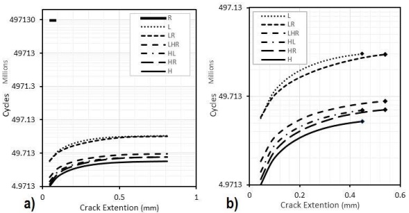
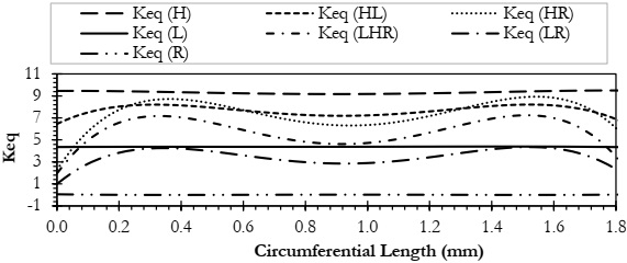
The cycles for crack growth have been shown as curves in Figure 14 obtained from ANSYS SMART crack growth simulations for different orientations. These results state that the crack in H orientation exhibited the lowest cycles because the affective stress in H orientation is hoop which is the highest stress as compared to the other two and conversely, the number of cycles is highest for R orientation which is a dead orientation. After all, the solution stops in the first step even at a very fine mesh justifying no crack growth in plane perpendicular to radial stresses as it is compressive stress as shown in Figure 7 leading to no crack growth when the tube is pressurized internally. The crack growth is along the x-axis of each crack coordinate and thus the solution for a number of cycles has been shown till the final leak in Figure 14b. It shows that as the influence of hoop stress increases across a crack plane the number of cycles decreases.

Figure 14: (a). Crack Extension and Cycles for Different Orientations. (b). Cycles to Leak

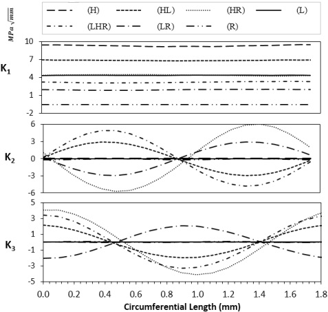
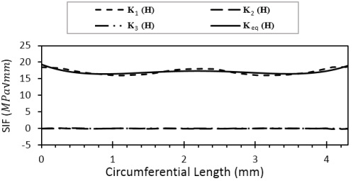
Figure 15 shows the SIFs in modes 1, 2, and 3 respectively, and the equivalent SIF is shown in Figure 16 in the first step. These figures show that mode 1 SIF is the dominant one and has the higher value for (H). The elevated value observed can be attributed to the predominance of hoop stress, which surpasses other stress components, as previously outlined. By comparing Figure 14 and Figure 16 we can say that the higher the equivalent stress intensity factor lower the cycles to failure.

Figure 15: Mode 1, 2, and 3 SIFs for all Cracks around the Circumferential Length at Step 1

Figure 16: Equivalent SIF for all cracks around the circumferential length at Step 1

Figure 17 shows the SIFs for (H) in step ten just before the final leak where the SIFs have been increased as compared to step one. This increase is due to the change in crack dimensions which increases in each step and so as an equivalent stress intensity factor K_eq.

Figure 17: Mode 1, 2, and 3 SIF for crack with H orientation

Conclusion

Generally, the SIF is higher at the major axis and lower at the minor axis of a semi-elliptical crack, irrespective of whether the crack is in a simple cube or a different geometry. In a non-uniform stress distribution, the variation of SIF across the crack front can be complex and depends on the specific stress distribution. It cannot be simply generalized as lower on the major axis and higher on the minor axis. The loading cycles required for the specific crack growth are higher for the outer crack and lower for the inner crack with Simpson’s integration of Paris’s law. Thus, the inner surface crack grows faster as compared to the outer surface.

The crack grows faster when the crack is perpendicular to the hoop stress in the wall. This is because the hoop stress is higher as compared to longitudinal and radial stress. And the higher value of stress causes a higher value of equivalent stress intensity factor which in turn dictates the crack growth. Other orientations that have the hoop stress component along the radial and longitudinal components showed relatively higher crack growth. When a crack plane is normal to the radial stress the only stress acting is radial, the crack growth is much slower. We can call this plane a dead plane where no crack growth is possible and that is because the gradient of radial stresses across the wall is negative and thus in compression. But a plane oriented at 45 degrees to the radial stresses and 45 degrees to hoop stresses would have higher Mode 1 and 2 stress intensity factors associated with it resulting in high equivalent stress intensity factors. Thus, there would be higher crack growth. A mathematical model has been discussed for crack growth in pressure vessels like pipes and tubes. Finally, it is conclusive that changing the location and orientation of the same crack in a tube will affect the crack growth. Therefore, upon detection of a crack, location, and orientation should be considered to determine the remaining life of a boiler tube by utilizing ANSYS SMART because the size of the crack is not the only parameter to retire structures that have strategic importance.

Acknowledgment: Gratitude to IAA, Air University Islamabad

Author’s Contribution: Each author contributed equally.

Conflict of Interest: The authors declare no conflict of interest in publishing this manuscript in IJIST.

Reference

[1] “Experimental investigation of boiler blast load on building structures.” Accessed: Mar. 18, 2024. [Online]. Available: http://lib.buet.ac.bd:8080/xmlui/bitstream/handle/123456789/6243/Full Thesis.pdf?sequence=1&isAllowed=y

[2] A. R. Paul, F. Alam, A. Jain, and M. S. Ali, “Boiler Safety in South Asia,” J. Inst. Eng. Ser. C, vol. 101, no. 5, pp. 761–769, Oct. 2020, doi: 10.1007/S40032-020-00597-0/METRICS.

[3] C. Bierl, “Boiler and Pressure Vessel Safety, Hazards in the Workplace!” OnePetro, Jun. 19, 2017. Accessed: Mar. 18, 2024. [Online]. Available: https://dx.doi.org/

[4] A. Toudehdehghan and T. W. Hong, “A critical review and analysis of pressure vessel structures,” IOP Conf. Ser. Mater. Sci. Eng., vol. 469, no. 1, p. 012009, Jan. 2019, doi: 10.1088/1757-899X/469/1/012009.

[5] K. R. Golwalkar and R. Kumar, “Pressure Vessels,” Pract. Guidel. Chem. Ind., pp. 55–80, 2022, doi: 10.1007/978-3-030-96581-5_4.

[6] D. Ghosh, H. Roy, A. Saha, and C. Subramanian, “Failure Analysis of Boiler Water Wall Tube: A Case Study from Thermal Power Plant,” J. Fail. Anal. Prev., vol. 22, no. 1, pp. 203–208, Feb. 2022, doi: 10.1007/S11668-021-01271-Y/METRICS.

[7] E. Febriyanti, A. Suhadi, and L. N. Sari, “FATIGUE AND CORROSION PHENOMENON ON FAILURE OF WATER WALL TUBE BOILER,” Maj. Ilm. Pengkaj. Ind. J. Ind. Res. Innov., vol. 14, no. 1, pp. 29–38, Sep. 2020, doi: 10.29122/MIPI.V14I1.3565.

[8] F. Bjørheim, S. C. Siriwardane, and D. Pavlou, “A review of fatigue damage detection and measurement techniques,” Int. J. Fatigue, vol. 154, p. 106556, Jan. 2022, doi: 10.1016/J.IJFATIGUE.2021.106556.

[9] “API 579-1 FFS Features in INSPECT - Codeware.” Accessed: Mar. 18, 2024. [Online]. Available: https://www.codeware.com/products/inspect/api-579-1/?gad_source=1

[10] R. Usamentiaga, D. G. Lema, O. D. Pedrayes, and D. F. Garcia, “Automated surface defect detection in metals: A comparative review of object detection and semantic segmentation using deep learning,” Conf. Rec. - IAS Annu. Meet. (IEEE Ind. Appl. Soc., vol. 2021-October, 2021, doi: 10.1109/IAS48185.2021.9677231.

[11] R. Sui, Y. Zhao, B. Ge, and W. Wang, “Failure analysis of leakage at tube-to-tubesheet joints of a waste heat boiler,” Eng. Fail. Anal., vol. 129, p. 105639, Nov. 2021, doi: 10.1016/J.ENGFAILANAL.2021.105639.

[12] E. S. Kim, “Fracture analysis of tube boiler for physical explosion accident,” Forensic Sci. Int., vol. 278, pp. e1–e7, Sep. 2017, doi: 10.1016/J.FORSCIINT.2017.07.036.

[13] N. H. Lee, S. Kim, B. H. Choe, K. B. Yoon, and D. il Kwon, “Failure analysis of a boiler tube in USC coal power plant,” Eng. Fail. Anal., vol. 16, no. 7, pp. 2031–2035, Oct. 2009, doi: 10.1016/J.ENGFAILANAL.2008.12.006.

[14] N. V. Challenger, R. Phaal, and S. J. Garwood, “Fracture mechanics assessment of industrial pressure vessel failures,” Int. J. Press. Vessel. Pip., vol. 61, no. 2–3, pp. 433–456, Jan. 1995, doi: 10.1016/0308-0161(94)00120-8.

[15] A. Malik, A. Meroufel, and S. Al-Fozan, “Boiler Tubes Failures: A Compendium of Case Studies,” J. Fail. Anal. Prev., vol. 15, no. 2, pp. 246–250, Apr. 2015, doi: 10.1007/S11668-015-9923-X/METRICS.

[16] “Materials Science and Engineering”, [Online]. Available: https://www.wiley.com/en-gb/Callister%27s+Materials+Science+and+Engineering%2C+Global+Edition%2C+10th+Edition-p-9781119453918

[17] T. L. Anderson, “FRACTURE MECHANICS: Fundamentals and Applications, Fourth Edition,” Fract. Mech. Fundam. Appl. Fourth Ed., pp. 1–661, Jan. 2017, doi: 10.1201/9781315370293/FRACTURE-MECHANICS-TED-ANDERSON.

[18] N. Pugno, M. Ciavarella, P. Cornetti, and A. Carpinteri, “A generalized Paris’ law for fatigue crack growth,” J. Mech. Phys. Solids, vol. 54, no. 7, pp. 1333–1349, Jul. 2006, doi: 10.1016/J.JMPS.2006.01.007.

[19] D. Rozumek and E. MacHa, “A survey of failure criteria and parameters in mixed-mode fatigue crack growth,” Mater. Sci., vol. 45, no. 2, pp. 190–210, Mar. 2009, doi: 10.1007/S11003-009-9179-2/METRICS.

[20] H. Yuan, W. Yang, L. Zhang, and T. Hong, “Model Development of Stress Intensity Factor on 7057T6 Aluminum Alloy Using Extended Finite Element Method,” Coatings 2023, Vol. 13, Page 581, vol. 13, no. 3, p. 581, Mar. 2023, doi: 10.3390/COATINGS13030581.

[21] “AFGROW (Air Force Growth) Fracture Mechanics and Fatigue Crack Growth Analysis Software - Home Page.” Accessed: Mar. 18, 2024. [Online]. Available: https://www.afgrow.net/

[22] Y. A. Fageehi and A. M. Alshoaibi, “Nonplanar Crack Growth Simulation of Multiple Cracks Using Finite Element Method,” Adv. Mater. Sci. Eng., vol. 2020, 2020, doi: 10.1155/2020/8379695.

[23] D. D’Angela and M. Ercolino, “Fatigue crack growth in metallic components: numerical modeling and analytical solution,” Authorea Prepr., Jul. 2020, doi: 10.22541/AU.159493143.38339244.

[24] T. T. Htut et al., “Fatigue fracture investigation of a tube-to-tubesheet welded joint,” Eng. Struct., vol. 283, p. 115908, May 2023, doi: 10.1016/J.ENGSTRUCT.2023.115908.

[25] J. Niu and M. S. Wu, “Analysis of asymmetric kinked cracks of arbitrary size, location and orientation - Part I. Remote compression,” Int. J. Fract., vol. 89, no. 1, pp. 19–57, 1998, doi: 10.1023/A:1007428827074/METRICS.

[26] J. Niu and M. S. Wu, “Analysis of asymmetric kinked cracks of arbitrary size, location and orientation - Part II. Remote tension,” Int. J. Fract., vol. 89, no. 1, pp. 59–84, 1998, doi: 10.1023/A:1007476710235/METRICS.

[27] G. de C. Coêlho, A. A. Silva, M. A. Santos, A. G. B. Lima, and N. C. Santos, “Stress Intensity Factor of Semielliptical Surface Crack in Internally Pressurized Hollow Cylinder—A Comparison between BS 7910 and API 579/ASME FFS-1 Solutions,” Mater. 2019, Vol. 12, Page 1042, vol. 12, no. 7, p. 1042, Mar. 2019, doi: 10.3390/MA12071042.

[28] S. A. Ligoria, G. M. S. Knight, and D. S. Ramachandra Murthy, “Three-dimensional Finite Element Analysis of a Semi-Elliptical Circumferential Surface Crack in a Carbon Steel Pipe Subjected to a Bending Moment,” http://dx.doi.org/10.1243/030932405X16052, vol. 40, no. 6, pp. 525–533, Aug. 2005, doi: 10.1243/030932405X16052.

[29] “Metallography and Microstructures,” Metallogr. Microstruct., Dec. 2004, doi: 10.31399/ASM.HB.V09.9781627081771.

[30] C. D. Wallbrink, D. Peng, and R. Jones, “Assessment of partly circumferential cracks in pipes,” Int. J. Fract., vol. 133, no. 2, pp. 167–181, May 2005, doi: 10.1007/S10704-005-0628-0/METRICS.

[31] A. Zareei and S. M. Nabavi, “Weight function for circumferential semi-elliptical cracks in cylinders due to residual stress fields induced by welding,” Arch. Appl. Mech., vol. 86, no. 7, pp. 1219–1230, Jul. 2016, doi: 10.1007/S00419-015-1087-3/METRICS.

[32] S. Melin, “Which is the most unfavourable crack orientation?,” Int. J. Fract., vol. 51, no. 3, pp. 255–263, Oct. 1991, doi: 10.1007/BF00045811/METRICS.

[33] D. L. McDowell, “Basic issues in the mechanics of high cycle metal fatigue,” Int. J. Fract., vol. 80, no. 2, pp. 103–145, Apr. 1989, doi: 10.1007/BF00012666/METRICS.

[34] A. Karolczuk and E. Macha, “A review of critical plane orientations in multiaxial fatigue failure criteria of metallic materials,” Int. J. Fract., vol. 134, no. 3–4, pp. 267–304, Aug. 2005, doi: 10.1007/S10704-005-1088-2/METRICS.

[35] A. Moftakhar, A. Buczynski, and G. Glinka, “Calculation of elasto-plastic strains and stresses in notches under multiaxial loading,” Int. J. Fract., vol. 70, no. 4, pp. 357–373, Dec. 1994, doi: 10.1007/BF00032453/METRICS.

[36] M. Kamaya and T. Kitamura, “Stress intensity factors of microstructurally small crack,” Int. J. Fract., vol. 124, no. 3–4, pp. 201–213, 2003, doi: 10.1023/B:FRAC.0000018238.41283.A4/METRICS.

[37] “Simulate of edge and an internal crack problem and estimation of stress intensity factor through finite element method.” Accessed: Mar. 18, 2024. [Online]. Available: https://www.techno-press.org/content/?page=article&journal=anr&volume=12&num=4&ordernum=6

[38] O. Elmhaia, Y. Belaasilia, O. Askour, B. Braikat, and N. Damil, “An efficient mesh-free approach for the determination of stresses intensity factors,” Eng. Anal. Bound. Elem., vol. 133, pp. 49–60, Dec. 2021, doi: 10.1016/J.ENGANABOUND.2021.08.001.

[39] P. K. Pati, S. K. Shrivastava, and S. Basu, “Numerical analysis of crack initiation and growth in cylindrical geometries with an axial flaw,” Int. J. Fract., vol. 148, no. 4, pp. 291–301, Dec. 2007, doi: 10.1007/S10704-008-9202-X/METRICS.

[40] C. D. M. O. Ranaraja, J. W. Devasurendra, M. I. P. Maduwantha, G. A. L. Madhuwantha, and R. Y. D. Hansa, “Optimization of an Industrial Boiler Operation,” J. Res. Technol. Eng., vol. 1, 2020.

[41] A. Chaudouet, F. Osweiller, P. Hanmore, and G. G. Karcher, “Perspectives of the Pressure Equipment Directive with Respect to ASME BPVC,” Companion Guid. to ASME Boil. Press. Vessel Code, Vol. 3, Third Ed., pp. 129–157, Nov. 2009, doi: 10.1115/1.802717.CH47.

[42] I. Mazínová and P. Florian, “Materials selection in mechanical design,” Lect. Notes Mech. Eng., vol. 16, pp. 145–153, 2014, doi: 10.1007/978-3-319-05203-8_21.

[43] ASME (American Society of Mechanical Engineers), “Asme Bpvc,” Asme Boil. Press. Vessel Code, 2015.

[44] “Shigley’s Mechanical Engineering Design - Richard Budynas, Keith Nisbett - Google Books.” Accessed: Mar. 18, 2024. [Online]. Available: https://books.google.com.pk/books/about/Shigley_s_Mechanical_Engineering_Design.html?id=B7wivgAACAAJ&redir_esc=y

[45] D. Annaratone, “Pressure vessel design,” Press. Vessel Des., pp. 1–443, 2007, doi: 10.1007/978-3-540-49144-6/COVER.

[46] “Polar contour plot - File Exchange - MATLAB Central.” Accessed: Mar. 18, 2024. [Online]. Available: https://www.mathworks.com/matlabcentral/fileexchange/14826-polar-contour-plot

[47] X. R. Wu and W. Xu, “Weight Function Methods in Fracture Mechanics: Theory and Applications,” Weight Funct. Methods Fract. Mech. Theory Appl., pp. 1–654, Jan. 2022, doi: 10.1007/978-981-16-8961-1/COVER.

[48] “WEIGHT FUNCTION METHODS AND ASSESSMENT FOR AN EDGE CRACK IN A SEMI-INFINITE PLATE 1,” vol. 49, no. 4, pp. 848–857, 2017, [Online]. Available: https://pubs-en.cstam.org.cn/article/doi/10.6052/0459-1879-17-024

[49] “Universal features of weight functions for cracks in mode I - ScienceDirect.” Accessed: Mar. 18, 2024. [Online]. Available: https://www.sciencedirect.com/science/article/abs/pii/0013794491901773?via%3Dihub

[50] U. A. Campos and D. E. Hall, “Simplified Lamé’s equations to determine contact pressure and hoop stress in thin-walled press-fits,” Thin-Walled Struct., vol. 138, pp. 199–207, May 2019, doi: 10.1016/J.TWS.2019.02.008.

[51] X. J. Zheng, A. Kiciak, and G. Glinka, “Weight functions and stress intensity factors for internal surface semi-elliptical crack in thick-walled cylinder,” Eng. Fract. Mech., vol. 58, no. 3, pp. 207–221, Oct. 1997, doi: 10.1016/S0013-7944(97)00083-0.

[52] C. P. Andrasic and A. P. Parker, “Dimensionless stress intensity factors for cracked thick cylinders under polynomial crack face loadings,” Eng. Fract. Mech., vol. 19, no. 1, pp. 187–193, Jan. 1984, doi: 10.1016/0013-7944(84)90078-X.

[53] S. R. Mettu, I. S. Raju, and R. G. Forman, “Stress Intensity Factors for Part-Through Surface Cracks in Hollow Cylinders.” 1992.

[54] V. Vullo, “Circular Cylinders and Pressure Vessels,” vol. 3, 2014, doi: 10.1007/978-3-319-00690-1.