
Compact Frequency Selective Surface (FSS) for X-Band Shielding
Taiba Khalil1, Muhammad Ali Riaz1, Humayun Shahid1, Muhammad Jamil Khan1, Yasar Amin1
1 Department of Telecommunication Engineering (University of Engineering and Technology Taxila).
* Correspondence: Taiba Khalil, Email: taiba.khalil14@gmail.com
Citation | Khalil. T, Riaz. M. A, Khan. M. J and Amin. Y, “Compact Frequency Selective Surface (FSS) for X-Band Shielding”. International Journal of Innovations in Science and Technology, Special Issue, pp: 140-152, 2021.
Received | Dec 01, 2021; Revised | Dec 22, 2021 Accepted | Dec 26, 2021; Published | Jan 06, 2022.
Abstract.
With the increase in the usage of electromagnetic devices, electromagnetic interference increased many folds. Frequency Selective Surface (FSS) provide effective shielding from unwanted frequency ranges. A thin, conformal band-stop FSS is presented in this research that provides effective electromagnetic shielding properties in X-band. The FSS acts as a band stop filter at 10 GHz. The proposed FSS has 54.7% fractional bandwidth. The design is of the dimensions 6.79 x 6.79 x 0.127 milli meter cube, employing Rogers RT 5880 substrate with 0.0009 dielectric constant. It has an attenuation of at least -57.97 dB. The proposed FSS shows oblique incidence angle independence for both TE and TM modes, up to 60o scan angle. The incidence angle independence makes the FSS response stable for both normal and varying angles of the incident waves. The design has a copper cladding of 0.018 mm, making the overall FSS thickness of 0.145 mm. The thin substrate makes the design flexible and easily bendable for curved surfaces. Its thin structure makes it easily applicable on buildings, vehicles and military aircrafts for electromagnetic shielding purposes. The conformability and shielding properties make the design suitable for various other applications.
Keywords: Frequency Selective Surface; X-Band; Electromagnetic Shielding; Flexible; compact.
INTRODUCTION
Rapid technological enhancements and the invention of smart devices have connected several devices with each other. This device-to-device connectivity and various other technologies like the Internet of Things (IoT), space communication and radars have increased the electromagnetic interference. 5G also aims to provide a huge data rate with less latency, [1,2] increasing the electromagnetic interference. X-Band (8-12 GHz) is one of the major contributors to increasing electromagnetic interference [3]. X-Band frequency ranges are immune to atmospheric attenuation which makes them ideal for weather monitoring and space communication. It has a shorter wavelength and higher image resolution for radar applications, maritime traffic control and vehicle detection [4]. Electromagnetic interference causes serious threats to sensitive electronic systems, healthcare and military devices. The electromagnetic interference can be minimized by using effective shielding, for example metallic shields can be used for isolation from electromagnetic signals. But they block the desired electromagnetic radiations as well [5].
FSS provides effective shielding properties that can be used for shielding against the electromagnetic radiations owing to their selective filtering properties. FSS are periodic surfaces having identical elements in an infinite array arranged in one or two dimensions [6]. FSS has the capability of passing and blocking frequencies of desired range [7]. An array of periodic metallic patches or apertures on a dielectric substrate forms a frequency selective surface. The metallic apertures act as band pass filters, and the metallic patches act as bandstop filters at resonance frequency [8].
FSS can be used as polarizers, sub reflectors, filters, beam multiplexers in optical and microwave applications. Dual-band FSS for GSM shielding based on the paper substrate is presented to ensure effective shielding, having a low profile at affordable cost. A dual layer absorptive/transmissive FSS is proposed absorbing WLAN signals and transmitting GSM signals with reduced multipath fading [9]. FSS can be made electronically switchable by making it switch from transparent and reflection state. This makes it a spatial filter for reconfiguring building architecture [10]. FSS is known as spatial filters as they are different from classical filters. FSS deals with signals having different polarizations and angles of incidence [6]. Its capability to show a stable response for various incident angles for TM and TE modes makes it an excellent tool for use in Electromagnetic Compatible (EMC) applications, where polarization modes and angles are usually unknown [11]. A spiral slot frequency selective surface filter for shielding from undesired electromagnetic noise produced by wireless charging batteries is proposed in reference [12]. Spiral slot with seven to ten windings is cut on the metallic ground plane. The helical antenna is composed of five wire windings and the FSS is placed in between two helical antennas. FSS and Substrate Integrated Waveguide (SIW) technology is used for airborne radome applications [13,14].
The Electromagnetic Band Gap (EBG) structures can be used to suppress waves in the desired stop band. A hybrid of FSS and EBG is used to suppress surface waves [15]. Previously, multi-layer FSS was presented for shielding purposes in applications. Two FSS were cascaded using Koch fractal elements for shielding, and providing 20 dB attenuation with a wide stopband [16]. Multi-layer FSS structures needed to be carefully aligned and more FSS layers might cause processing errors [17]. Extremely High Frequency (EHF) ranges are used in transmitters of satellites, which increases the electromagnetic interferences and it can damage sensitive external transceivers. Due to a large number of transmitters and receivers outside the satellite, satellites can get interference from nearby transmitters. 2D cross-dipole FSS structure with specific stop band property can be used for shielding against out-of-band signals [18]. Miniaturized FSS for shielding in the millimeter wave region (40 – 70 GHz) is presented in reference [19]. The structure is single layered having Jerusalem cross and Fan shape etched on both sides of the substrate. It has a shielding effectiveness of more than 16 dB and can be used for mutual coupling reduction. FSS is analyzed in terms of its S-Parameters, polarization independence and shielding effectiveness. Various methods have been used for calculating the shielding effectiveness of an enclosure. The transmission line approach for calculating the shielding effectiveness of a double layer frequency selective surface enclosure, with different angles of incidence is much faster than other numerical methods [20].
FSS can be made flexible by using flexible substrate; it can provide conformal shielding by using it on curved surfaces. Stretchable FSS embedded with silicone elastomers are able to be wrapped on doubly curved surfaces [21]. FSS shielding for X band by using miniature ring shaped elements was proposed in [22]. Effective shielding in X and Ka bands were achieved by a single layer Ultra-Wide Band (UWB) polarization stable FSS [23]. Shielding in X-band is of immense importance as it is used for communication and radar engineering. Gas plasma encapsulated in FSS with switchable attenuation from 24dB to 44dB is used for electromagnetic shielding in X-band. This low loss device has three orders of structure and a large area that makes it useful for beam steering and RCS control as well [24]. Compact FSS structure consisting of eight segment polygon having an attenuation of 35dB is used and presented for effective shielding in X-band. The structure shows polarization independence in TE and TM modes [25]. A convoluted ring loop FSS structure having a low profile is developed for X-band shielding. For miniaturization, four stubs are added at a 90o angle to each other. The structure has an attenuation of 37 dB for a oblique angle of incidence up to 45o [26]. A sub-wavelength polarization independent FSS for X-band shielding is proposed in reference [27]. It shows attenuation of greater than 25 dB for the shielding band. A FSS for shielding X-band SATCOMS is proposed in reference [28]. It shows bandstop characteristics with attenuation of up to 32 dB in the shielding band. An FSS consisting of a convoluted circular loop for electromagnetic shielding applications is proposed in reference [29, 30, 31]. Its effective shielding is centered at 9.7 GHz with an attenuation of atleast 47 dB [32, 33].
The proposed design of this study was comprised of a thin FSS layer printed on Rogers’s 5880 substrate having a thickness of 0.127 mm. The thin dielectric substrate makes the structure flexible, making it easier to employ on curved surfaces. The design stops the frequency at 10 GHz (X-band) and transmits the rest of the frequency ranges. It has an attenuation of at least -57.97 dB. The proposed design shows oblique incidence angle independence in terms of both TE and TM modes for up to scan angle of 60o. The design consists of a compact unit cell to provide stability for various incidence angles. It employs an extremely thin substrate that is highly flexible and easily applicable on curved surfaces. It can be used in antennas for enhancing the gain and directivity of antenna.
Material and methods.
The proposed design is simulated on Rogers 5880 substrate in Figure. 1 and 2. The substrate has a dielectric loss tangent of 0.0009 and relative permittivity of 2.2. The thickness of substrate is 0.127 mm that makes the FSS flexible. The overall unit cell has dimensions of 6.79 x 6.79 millimeter square. The design consists of an X-shaped metallic loop placed on the substrate. The proposed design is printed on one side of the dielectric substrate. The thickness of copper cladding is 18 micro meter.
The parameter ‘P’ represents the length and width of the substrate and ‘L’ represents the length and width of the metallic X-shaped square loop. The design consists of V-shaped inward stubs on all sides of the square loop. The design parameters are given in Table 1. The positioning and size of these stubs provide the incidenceangle independent in terms of TE and TM modes.
 .
.
Figure 1. Proposed FSS Unit Cell Front View
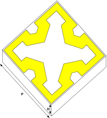
Figure 2. Proposed FSS Unit Cell Perspective View
Table 1. Parameter List
|
Parameter |
Value(mm) |
|
P |
6.79 |
|
L |
6.6 |
|
G |
1.12 |
|
R |
0.935 |
|
W |
0.56 |
|
H |
0.127 |
Result and discussion.
Ansoft HFSS was used for simulation and optimization of the proposed design. The proposed FSS is designed in order to shield against frequencies in the X-band (8-12 GHz). S11 and S21 parameters were calculated for the normal angle of incidence in Figure 3. Shielding effectiveness (SE) of the proposed design was calculated for checking shielding against X-band shown in Figure 4. The design shows good shielding properties for X-band with its resonance frequency at 10 GHz. It has an attenuation of at least -57.97 dB.
Oblique Incidence Angle Independence - The design showed independence for oblique angles of incidence for both TE and TM modes. Figure 5 shows SE of TE and TM modes, for the angle of incidence up to 60o. The polarization independence was provided with the help of V-shaped stubs pointed inwards in the square loop. The widths of these stubs affect the response of FSS, for different incident angles. The fractional bandwidth increased slightly with the increase in the angle of incidence for TE modes in Figure 5. The fractional bandwidth decreased with the increase in the angle of incidence for TM modes in Figure 6.
The change in the resonant frequency was not significant for the change in angle of incidence for both TE and TM modes. The resonant frequency remains in the allowable limits for both TE and TM modes, by changing the angles of incidence up to 60o. A few abnormalities were observed from 15.1 GHz to 18 GHz in case of TE modes because of the varying angle of the incident wave. The angles greater than 30o interferes with the higher frequency range of X-band. It showed minor shielding effects for attenuation up to 27 dB for scan angle of 30o and up to 45 dB for the scan angle of 60o.
Effects of Varying Length i.e a A frequency shift was observed in the resonance frequency by varying the length of the inner copper loop ‘L’ in Figure 7. By increasing ‘L’ from 6.6 mm to 6.7 mm, the resonant frequency shifts to the lower frequency range, from 10 GHz to 8.36 GHz. By decreasing ‘L’ from 6.6 mm to 6.4 mm, the resonant frequency shifts to a higher frequency range of 10 GHz to 11.52 GHz. In this case the frequency shift was indirectly proportional to varying ‘L’. The frequency shift can also be observed by varying the thickness of the hexagonal stubs ‘G’ in Figure 8.
By increasing ‘G’ from 1.08 mm to 1.12 mm, the resonant frequency shifted to a lower frequency range, from 10 GHz to 9.57 GHz. In this case, the frequency shift was directly proportional to ‘G’. However, the frequency shift was slightly smaller for varying ‘G’ than ‘L’.
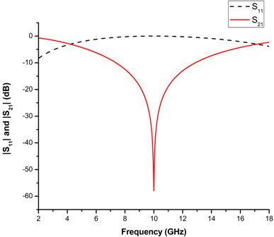
Figure 3. S11 and S21 Parameter

Figure 4. Shielding Effectiveness
Loss Tangent – The loss tangent of the employed substrate affected the SE of the proposed FSS in Figure 9 by varying loss tangent Sigma, due to which the SE value also varies. When Sigma=0 the SE reaches to the maximum value of -57.97 dB. By increasing Sigma from 0 to 1 the SE starts decreasing until it reaches to the minimum value of Sigma =1. For the proposed design Sigma=0.0009 for Rogers 5880 substrate.
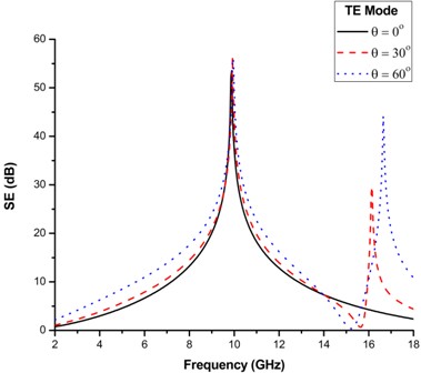
Figure 5 Effects of Varying Angles of Incidence on Proposed FSS for TE Modes.

Figure 6 Effects of Varying Angles of Incidence on Proposed FSS for TM Modes
Relative Permittivity – The relative permittivity used for the proposed design is 2.2. By increasing the relative permittivity, the resonant frequency was shifted to the lower frequency range as shown in Figure 10. For the increase in the relative permittivity, from 2.2 to 6.2, the resonant frequency shifts from 10 GHz to 7.5 GHz. For the decrease in the relative permittivity from 2.2 to 1.2, the frequency shifted to the higher frequency range at 10.78 GHz. The frequency shift was indirectly proportional to the relative permittivity.
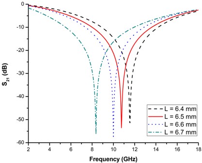
Figure 7. Varying length of square loop ‘L’

Figure 8. Varying Length of hexagonal stub ‘G’
Fss Prototype Fabrication - The proposed FSS design was fabricated on a Rogers RT 5880 substrate sheet of 9 x 12 inches. The copper patch on the substrate was 18 micro meter in thickness. The FSS prototype was fabricated by etching the metallic patch on the substrate. The FSS unit cells were of the order 33 x 44 across the sheet as shown in Figure 11.
The proposed design was compared with other studies in the relevant field in Table. II. The results shows that the proposed FSS is thinnest among others, making it extremely flexible and applicable on curved surfaces.

Figure 9. SE by varying loss tangent

Figure 10. Frequency shift by varying permittivity

Figure 11. Fabricated FSS Prototype
Table 2. Comparison
|
Reference |
Substrate |
Size (mm3) |
FSS Sheet Thickness (mm) |
Oblique Incidence Angle Independence |
Flexible |
|
30 |
FR4 |
12x12x3.2 |
3.235 |
Up to 450 |
No |
|
31 |
Arlon Di880 |
8.8x8.8x0.762 |
0.762 |
Up to 600 |
No |
|
32 |
FR4 |
10x10x0.7 |
0.797 |
No |
No |
|
33 |
Rogers 5880 |
6.8x6.8x0.127 |
0.162 |
Up to 600 |
Yes |
|
25 |
FR4 |
5.3x5.3x1.6 |
1.635 |
Up to 600 |
No |
|
22 |
FR4 |
7.1x7.1x1.6 |
1.635 |
Up to 450 |
No |
|
Proposed Work |
Rogers 5880 |
6.79x6.79x0.127 |
0.145 |
Up to 600 |
Yes |
|
|
|
|
|
Conclusion.
An FSS for X-band shielding is proposed. The design is of 6.79 x 6.79 x 0.127 milimeter cube dimensions. The proposed FSS show attenuation of at least -57.97 dB with a fractional bandwidth of 54.7 %. The FSS absorbs the frequency at 10 GHz and transmits the rest of the frequency ranges. The design is oblique incident angle independent in terms of TE and TM modes up to a scan angle of 60o. The proposed design is extremely thin and flexible which makes it easily applicable on curved surfaces. It can be used in antennas to gain enhancement due to its reflective properties. It can be used in radomes, aircrafts and buildings for shielding purposes.
Acknowledgement.
All admires and thankfulness to Almighty Allah who gave me wisdom and knowledge to explore the world. I am thankful to my Research Project Supervisor Engr. Dr. Muhammad Ali Riaz for his aspiring guidance and kind advice during the project work. I am sincerely grateful to Engr. Dr. Humayun Shahid for his precious time that he gave me during the completion of my project and friendly advice whenever I needed his help. I am thankful to my family for their endless love and support during my work.
Author’s Contribution.
The concept and idea of research was suggested by Dr. Muhammad Ali Riaz. The whole research and paper writing was performed under his supervision and reviewed by him. Taiba Khalil designed the proposed FSS and performed simulations to get the required results. She also wrote the research paper under the guidance of Dr. Humayun Shahid. The softwares used for the simulations are provided by Dr. Yasar Amin and Dr. Muhammad Jamil Khan.
Project details. The research was done for completion of Masters in Engineering Research Project. Total amount spent on project in 8000 PKR, for dielectric substrate and fabrication of the FSS Sheet. The project was completed in February 2019.
Conflict of interest. There is no conflict of interest for submitting this paper to IJIST.
REFRENCES
- Sani Yahya, M., and Rahim, SKA, “15 GHz grid array antenna for 5G mobile communications system,” Microwave and OpticalTechnology Letters, 2016, vol. 58, no. 12, pp. 2977–2980.
- Hakimi, S., Rahim, S. K. A, “Millimeter-wave microstrip Bent line Grid Array antenna for 5G mobile communication networks,” In Proceedingsof the IEEE Asia-Pacific Microwave Conference (APMC),Sendai, Japan, 2014, pp. 622–624.
- Bruder, J. A., Carlo, J., Gurney, J., Gorman, J “ IEEE standard for letter designations for radar-frequency bands,” IEEEAerospace & Electronic Systems Society, 2003, vol. 6, no. pp. 1– 3.
- Damini, A., McDonald, M., Haslam, G. E, “X-band wideband experimental airborne radar for SAR, GMTI and maritime surveillance,” IEE Proceedings-Radar, Sonar and Navigation, 2003, vol. 150, no. 4, pp. 305–312.
- Seman, F. C., Khalid, N. K, “Investigations on fractal square loop FSS at oblique incidence for GSM applications,” In IEEE ElectricalPower, Electronics, Communicatons, Control and Informatics Seminar(EECCIS), Malang, Indonesia, 2014, vol. 58, no. , pp. 62–66.
- Munk, B. A, “Frequency selective surfaces: theory and design,” New York (USA), John Wiley and Sons, 2005.
- Anwar, Rana, Mao, L., Ning, H, “Frequency selective surfaces: A review of Applied Sciences,” Microwave and Optical TechnologyLetters, 2018, vol. 8, no. 9, pp. 1689.
- Unal, E., Gokcen, A., Kutlu, Y, “ Effective electromagnetic shielding,” IEEE Microwave magazine, 2006, vol. 7, no. 4, pp. 48–54.
- Kiani, G. I., Weily, A. R., Esselle, K. P, “A novel absorb/transmit FSS for secure indoor wireless networks with reduced multipath fading,” IEEE Microwave andWireless Components Letters, 2006,vol. 16, no. 6, pp. 378–380.
- Kiani, G. I., Ford, K. L., Olsson, L. G., Esselle, K. P., Panagamuwa, C. J, “Switchable frequency selective surface for reconfigurable electromagnetic architecture of buildings,” IEEE Transactions on Antennas and Propagation, 2009, vol. 58, no. 2, pp. 581–584.
- Huang, F. C., Chiu, C. N., Wu, T. L., Chiou, Y. P, “A circularring miniaturized-element metasurface with many good features for frequency selective shielding applications,” IEEE Transactions onElectromagnetic Compatibility, 2015, vol. 57, no. 3, pp. 365–374.
- Firdaus, K., Sakakibara, K., Amano, Y., Hirayama, H., Kikuma, N., Tabata, T., Kojima, S. H, “Design of spiral-slot frequency selective surfaces for shielding from noises of wireless power transfer,” In Proceedings of the IEEE International Workshopon Antenna Technology (iWAT), South Korea., 2015, pp. 345–347.
- Kanth, V. K., Raghavan, S, “EM Design and Analysis of Frequency Selective Surface Based on Substrate-Integrated Waveguide Technology for Airborne Radome Application.,” IEEE Transactionson Microwave Theory and Techniques, 2019, vol. 67, no. 5, pp. 1727– 1739.
- Varikuntla, K. K., Velu, R. S, “Design and development of angularly stable and polarisation rotating FSS radome based on substrate-integrated waveguide technology,” IET Microwaves, Antennas and Propagation, 2019, vol. 13, no. 4, pp. 478–484.
- Varikuntla, K. K., Velu, R. S, “Design and development of angularly stable and polarisation rotating FSS radome based on substrate-integrated waveguide technology,” IET Microwaves, Antennas and Propagation, 2019, vol. 13, no. 4, pp. 478–484.
- Manicuba, R. H., D’Assuncao, A. G., Campos, A. L, “Wide stop-band cascaded frequency selective surfaces with Koch fractal elements,” In Digests of the 14th Biennial IEEE Conference on ElectromagneticField Computation, Chicago, IL, USA., 2010, vol. 16, pp. 1–1.
- Ma, X., Wan, G., Zhang, W., Mu, Y., Tang, X, “Synthesis of second-order wide-passband frequency selective surface using double- periodic structures,” IET Microwaves, Antennas and Propagation, 2006, vol. 13, no. 3, pp. 373–379.
- Turner, I, “Use of frequency selective surfaces to reduce coupling between antennas on satellites,” In Proceedingsof the IEEE International Symposium on Electromagnetic Compatibility (EMC), Dresden, Germany., 2015, pp. 340–343.
- Kesavan, A., Karimian, R., Denidini, T. A, “A novel wideband frequency selective surface for millimeter-wave applications,” IEEEAntennas and Wireless Propagation Letters, 2016, vol. 15, pp. 1711– 1714.
- Sureshkumar, T. R., Venkatesh, C., Salil, P., Subbarao, B, “Transmission line approach to calculate the shielding effectiveness of an enclosure with double-layer frequency selective surface,” IEEE Transactions on Electromagnetic Compatibility, 2015, vol. 57, no. 6, pp. 1736–1739.
- Gurrala, P., Oren, S., Liu, P., Song, J., Dong, L, “Fully conformal square-patch frequency-selective surface toward wearable electromagnetic shielding,” IEEE Antennas andWireless Propagation Letters, 2017, vol. 16, pp. 2602–2605.
- Yong, W. Y., Rahim, S. K. A., Seman, F. C., Ramili, M. R., Remili, N. A, “Miniaturisation of ring shape element frequency selective surface for X-band shielding,” In Proceedings of the IEEE AsiaPacific Microwave Conference (APMC), Kuala Lumpar, Malaysia., 2017, pp. 877–880.
- Sohail, I., Ranga, Y., Matekovits, L., Esselle, K. P., Hayt, S. G, “A low-profile single-layer UWB polarization stable FSS for electromagnetic shielding applications,” In Proceedings ofthe IEEE International Workshop on Antenna Technology: SmallAntennas, Novel EM Structures and Materials, and Applications(iWAT), Sydney, Australia., 2014, pp. 220–223.
- Cross, L. W, “Study of X-band plasma devices for shielding applications,” In Proceedings of the IEEE MTT-S International MicrowaveSymposium (IMS2014), Tampa, Florida, USA., 2014, pp. 1–4.
- Bilal, M., Saleem, R., Khan, F. A., Quddus, A., Shafique, M. F, “Frequency selective surface for X-band shielding applications,” In Proceedings of the IEEE 16th Mediterranean MicrowaveSymposium (MMS), Abu Dhabi, United Arab Emirates., 2016, pp. 1–3.
- Wu, G. Jiang, X. Wang, P. Xie and X. Li, "A Multi-Level-Denoising Autoencoder Approach for Wind Turbine Fault Detection," in IEEE Access, vol. 7, pp. 59376-59387, 2019
- Karamirad, C. Ghobadi, J. Nourinia, S. Abbasi and B. Mohammadi, "Sub-Wavelength Polarization-Independent Frequency Selective Surface for X-band Shielding," 2020 28th Iranian Conference on Electrical Engineering (ICEE), 2020, pp. 1-3.
- Bilal, R. A. Wagan, R. Saleem, A. Q. Satti, T. Shabbir and S. M. Abbas, "Fractal X-Shaped FSS Employed Electromagnetic Shield for X-band SATCOMs," 2020 IEEE International Symposium on Antennas and Propagation and North American Radio Science Meeting, 2020, pp. 993-994.
- Idrees, S. Buzdar, S. Khalid and M. A. Khalid, "A Novel Miniaturized Frequency Selective Surface for EMI Shielding Applications," 2021 International Bhurban Conference on Applied Sciences and Technologies (IBCAST), 2021, pp. 1003-1006.
- S. Syed, Y. Ranga, L. Matekovits, K. P. Esselle and S. Hay, "A Single-Layer Frequency-Selective Surface for Ultrawideband Electromagnetic Shielding," in IEEE Transactions on Electromagnetic Compatibility, vol. 56, no. 6, pp. 1404-1411, Dec. 2014
- Ünaldı, S. Çimen, G. Çakır and U. E. Ayten, "A Novel Dual-Band Ultrathin FSS With Closely Settled Frequency Response," inIEEE Antennas and Wireless Propagation Letters, vol. 16, pp. 1381-1384, 2017
- Sarika, R. Kumar, M. R. Tripathy and D. Ronnow, "Fractal frequency selective surface based band stop filters for X-band and Ku-band applications," 2017 3rd International Conference on Advances in Computing,Communication & Automation (ICACCA) (Fall), 2017, pp. 1-4
- Nauman, R. Saleem, A. K. Rashid and M. F. Shafique, "A Miniaturized Flexible Frequency Selective Surface for X-Band Applications," in IEEE Transactions on Electromagnetic Compatibility, vol. 58, no. 2, pp. 419-428, April 2016

Copyright by authors and 50Sea. This work is licensed under a Creative Commons Attribution 4.0 International License.