
Dual-Band 10-Element MIMO Antenna for Sub-6 GHz MIMO Applications in 5G Smartphones
Ali Sufyan1, Khan Bahadur Khan1, Waqar Aslam2, Yasir Salam3, Sundas Amin2
1Faculty of Engineering, The Islamia University of Bahawalpur, Bahawalpur, Pakistan.
2 Department of CS & IT, The Islamia University of Bahawalpur, Pakistan.
3 Department of Electrical Engineering, University of Sargodha, Sargodha, Pakistan.
* Correspondence: Ali Sufyan (ali.sufyan@iub.edu.pk)
Citation | Sufyan. A, Khan. B.K, Aslam. W, Salam. Y, Amin. S, “Dual-Band 10-Element MIMO Antenna for Sub-6 GHz MIMO Applications in 5G Smartphones”. International Journal of Innovations in Science and Technology. Vol 4, Issue 2, 2022, pp: 375-382
Received | March 10, 2022; Revised | April 10, 2022; Accepted | April 23, 2022; Published | April 25, 2022.
________________________________________________________________________
The dramatic growth of mobile users, IoT-based applications, and astounding channel capacity requirements to connect trillions of devices are some huge challenges of the previous mobile generations, 5G turned up the key solution. Although the 5G MIMO can boost channel capacity and spectrum efficiency, it is very challenging to integrate multiple antennas into a mobile phone with limited space. Therefore, we presented a multi-band 10-elements array antenna operating at the LTE (long term evolution) 42, 43, and 46 frequency spectrum (sub-6 GHz band) for MIMO applications in fourth/fifth generation (4G/5G) modern mobile phones in this paper. A simple T-shaped slot antenna is designed to acquire 10-element MIMO antenna implementation in LTE 42/43 and 46 bands. The presented antenna array is integrated using a low-priced FR-4 substrate which is typically used for 5.7- 6-inch smartphones and possesses dimensions of 150mm × 80mm × 0.8mm. The simulated results show superb impedance matching and isolation between ports (> -12 dB), radiation efficiency (>70 %), and Envelope Correlation Coefficient (ECC< 0.05) over the operational frequency. Consequently, the designed MIMO antenna array is effectively favorable for the 5G MIMO smartphone to enhance data output and the spectrum efficiency.
Keywords: LTE band 42/43 and 46; MIMO; 5G; dual-band; sub-6 GHz; Smartphones.
INTRODUCTION
The 5G multi-input multi-output (MIMO) is broadly famous for enhanced channel capacity and spectrum efficiency. The dramatic growth of mobile users, IoT-based applications, and astounding channel capacity requirements to connect trillions of devices are some huge challenges of the previous mobile generations. Hence, 5G turned up the key solution to meet these challenges by increasing the number of antennas in smartphones. The 5G smartphones are highly in demand during recent years as the world is in the deployment of 5G wireless networks which is occurring rapidly [1]. The developments in the mobile communication industry brought major challenges not only in system design where smartphones required integration of radio RF circuitry but also for the antennas supporting sub-6 GHz bands. This made antenna designing highly in demand and challenging, which can meet the user’s requirements such as compact and low-profile, sub-6 GHz MIMO applications compatibility, and reduced mutual coupling [2]–[4]. The projected upper capacity limit of an 8-element MIMO array through a minimum 20-dB SNR has been reported to reach up to 46 bits per second/ hertz, which magnifies the channel capacity constraint of 11.5 bps/Hz as compared to the standard 2×2 order MIMO network in the previous generations.
Several 5G MIMO array designs have been proposed for smartphones operating in the sub-6 GHz band recently [5]–[10]. Few antennas are operating at single-band and many others on multi-mode antenna types amongst already described antenna designs. Despite the fact, the hybrid dual 4G antennas (2×2 array) described in [9], which operate in conventional 4G (824–960 as well as 1710–2690 MHz) spectrum are together with an 8x8 MIMO antenna for fifth-generation smartphones which also counterbalance LTE 42 band, the antenna element itself is a single-band antenna and missing the LTE 43 frequency band. The work reported in [10], for 8×8 MIMO antenna for 5G multi-band works in the GSM 1900, LTE 2300, and LTE 2500. However, its multi-band operation is unable to cover the essential LTE 42, 43, and 46 bands for the upcoming sub- 6 GHz spectrum. Furthermore, the ground clearance areas are out-sized for implementation in the 5G mobile phones with narrow frames and large screens. A 10-element micro-strip line fed open slot antenna array was presented in [11], to attain a wide-ranging 6-dB impedance bandwidth that is capable of equally covering both the LTE 42 and 43 bands. The channel capacity of the reported 10 × 10 MIMO array at 20-dB SNR can extend up to 47 bps/Hz. Our referenced model [12], a 10-element antenna working in sub-6 GHz for MIMO Applications is not only covering the 3.5-3.7 GHz frequency spectrum but the extreme mutual coupling between the elements of an array is 10-dB that surely can disturb the performance of wireless communication system, phase, the amplitude of the radiators as well as the antenna efficiency.
Therefore, we proposed a dual-band, dual-mode 10-element antenna aimed at the 4G/5G smartphone in this paper. The dual-mode T-shaped slot antennas in the array are dual-band that is capable to cover the LTE 42/43 (3376–3790 MHz) band in the lower frequency spectrum, whereas the LTE 46 (5130–5984 MHz) band supports the upper-frequency spectrum. The polarization diversity and excellent isolation is attained by organizing the linearly polarized array of elements perpendicularly. Moreover, the main contribution of the presented work is the reduced size of the ground plane to achieve better performance and efficiency as compared to [12]. The projected array is simulated using CST Studio version 19, and to verify the MIMO antenna array performances parameters including S-parameters, ECC, and antenna efficiencies are also illustrated. Lastly, the antenna size is effectively reduced by cutting the horizontal edges of the ground to achieve better performance and efficiency.
ANTENNA DESIGN AND DIMENSIONS
To meet the arrangement of the downlink and uplink frequency spectrum LTE 42, 43, and 46, each antenna in the array can completely enfold the 3400–3800 MHz and 5150–5925 MHz frequency spectrum. Consequently, this 10- element MIMO antenna in the standard LTE 42/43 frequency spectrum for multiplexing and diversity implementation, the integrated array is equally functioning in LTE 46 band designed for mMIMO operation in LTE-LAA and LTE-U [13].
Proposed Antenna Geometry
The comprehensive arrangement of the slot antenna can be witnessed in Fig 1. As demonstrated the ground plane was firstly etched using a rectangular slot (16 mm ×2 mm) to function as the main radiator of the dual-band antenna. Then an open section of 0.5 mm × 0.5 mm on the thin strip was cut which is etched alongside the PCB, a T-shaped slot is designed on a narrow strip. Consequently, the thin strip is extended with two sections: the smaller and lengthier strip section with lengths L1 = 5.8 mm, and L2 = 9.7 mm respectively. Similarly, the size was reduced by cutting two open sections of 1 mm × 1 mm horizontally both on the left and the right sides which is less in size and complexity as depicted in Fig 2.
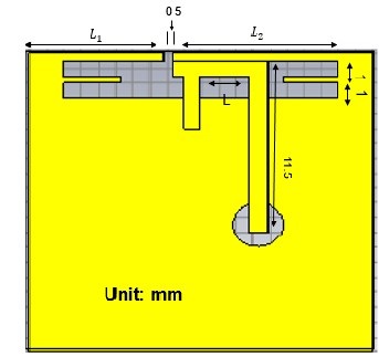
Figure 1. Proposed antenna.
Remarkably, just 3 mm size of the T-shaped slot represents that the suggested design is acceptable for the narrow frame mobile phones. At this point, on the opposite side of the ground, this T-slot is couple-fed with another T-shaped feed designed. The shorter feed-line involved two more vertical sections of 50- ohm micro-strip of size 11.5 mm × 1.5 mm and 3.5mm x 1.5 mm separated by a length L (4.50 mm x 1.5 mm) respectively. The slot parameters (L, L1, and L2) and the separation distances between them are accomplished by CST microwave studio version 19.
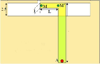
Figure 2. Referential case.
Array Configuration
The physical dimensions along with the geometry of the designed 10x10 MIMO array are presented in Figure 3. The 10 antennas are placed alongside the four edges (left, right, upper, and lower) using the well-known FR4 substrate for a 5.7 to 6-inch smartphone, having the typical size of 150mm × 80mm × 0.8mm with relative permittivity = 4.4 and loss tangent = 0.02.
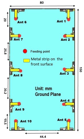
Figure 3. The structure and dimensions of the simulated 10x10 MIMO antenna array.
The substrate is PCB structure as the ground plane is produced on its rear side. The organization of this 10 x10 MIMO array is as follows. The upper and lower edges with four horizontal Ants 1,5, 6, and 10 and six vertical Ants 2- 4, and Ant 7- 9 are placed along with the two lengthy sideways, left, and right sides of PCB.
Table 1. List of Abbreviations
|
Definition |
Abbreviations |
|
Multi-input multi-output |
MIMO |
|
flame retardant -4 |
FR-4 |
|
Envelope Correlation Coefficient |
ECC |
|
radio frequency |
RF |
|
bits per second per hertz |
bps/Hz |
|
Long term evolution |
LTE |
|
LTE- Licensed Assisted Access |
LTE-LAA |
|
LTE-Unlicensed |
LTE-U |
|
massive MIMO |
mMIMO |
|
printed circuit board |
PCB |
|
Computer Simulation Technology studio |
CST Studio |
|
envelope correlation coefficient |
ECC |
|
signal-to-noise ratio |
SNR |
RESULTS
The result is depicted in this section thoroughly.
S-parameters
The designed 10-slot elements antenna is truly capable of working in the LTE 42/43/46 bands. The simulated results for reflection coefficients of the designed 10-element MIMO antenna exist in Fig. 4. For instance, the right and left side boundaries of the 10-element array antennas are symmetrically placed, simply the right side antenna elements results are displayed. To cover the higher and lower bands, two radiation modes of around 3.5 MHz and 5.5 MHz are produced. The design stacked at 8-dB impedance bandwidths is 3376–3790 MHz and 5130–5984 MHz respectively. The small frequency shift in the lower band is probably uncertain losses and connector effects.
The transmission coefficients of the simulated 10-slot antenna are illustrated in Fig. 5, which demonstrates that the isolation through the upper band is greater than 12.5 dB. Consequently, the separation distances among every two neighboring antennas are comparatively less, and this designed 10x10 MIMO antenna array illustrates decent isolation levels and impedance bandwidths.
The two vertical antennas (Ant 2 and 3) produced a poor performance with regards to reflection and transmission coefficient due to the symmetrical size of the patch length, which can be easily evaluated by the parametric sweep option in CST by varying the length of the patch and the simulated results are quite satisfactory in the domain of 5G MIMO antenna array design. The small dissimilarities of two vertical antennas (Ant 2 and 3) is also because of some uncertain losses. As shown in Fig.5, the effects of the coupling block on Ant 1, 2, 6, and 7 are still distinct.
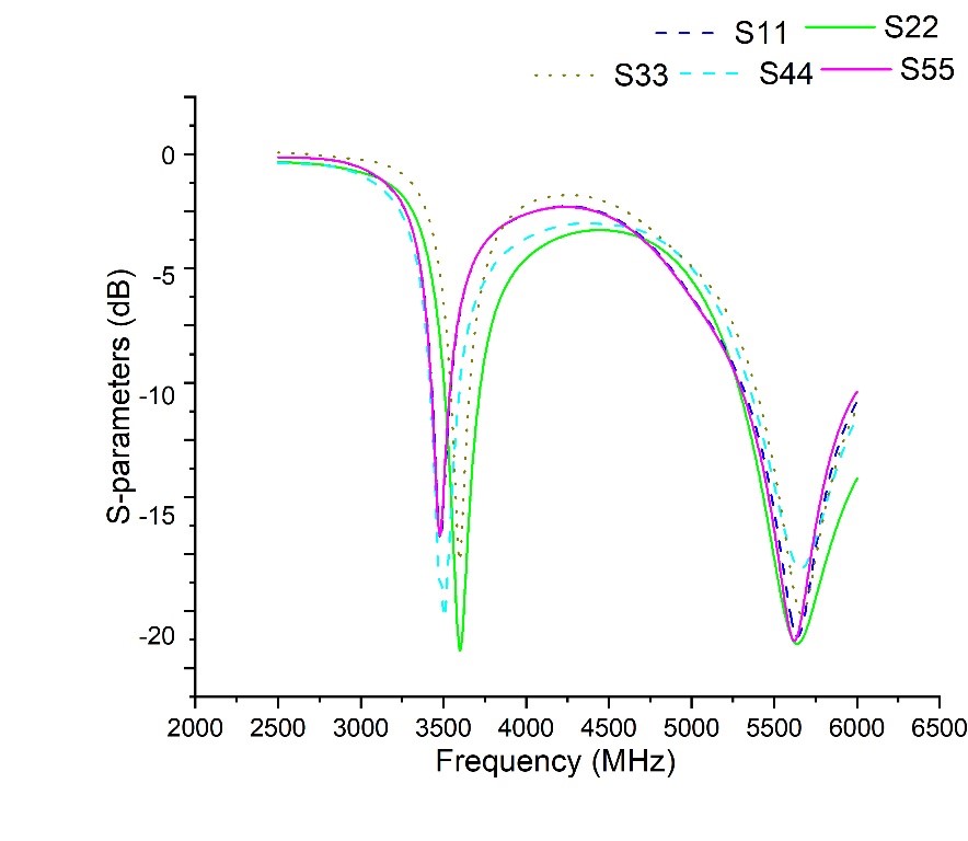
Figure 4. Reflection coefficients of the designed dual-mode 10-element MIMO antenna.
The simulated , and were superior to -11dB across the operational bandwidths. Moreover, the isolation of Ant 3 and 4 ( ) and Ant 6 and 1 ( are even greater than -17 dB in the lower frequency band.

Figure 5. S-parameters: Transmission coefficients of the proposed MIMO antenna.
Antenna Efficiencies
The total efficiencies of Ant 1-5 are depicted in Figure 6. The calculated efficiencies of the antennas through the lower and upper bands were 50 – 64% and 71–74%, respectively. To achieve low capacity losses greater than 40% and 60 % efficiencies, respectively, in both bands are required which proves that the achieved antenna efficiencies are still better[14].

Figure 6. Total efficiencies of Ant 1-5.
MIMO Performance
To authenticate the performance and capability of the proposed dual-Band antenna, it is compulsory to calculate a correlation between received signals at the equivalent side by the elaborated antenna. Most importantly, the low envelops correlation coefficient (ECC) < 0.5 is usually required to evaluate diversity performance. The ECC results of the proposed antenna are displayed in Fig.7 to estimate the multiplexing potential and diversity of the simulated 10-element MIMO antenna. By assuming, the transmission channel is constant, the ECC is calculated from the s-parameters by using equation (1) [15].
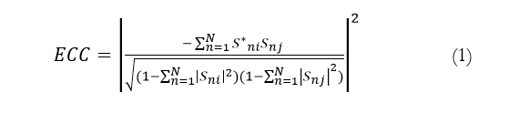
The estimated ECCs values were below 0.5 through the lower and higher frequency spectrum respectively. The calculated ECCs values of Ant 1 and Ant 6 were found relatively high during the whole operational bandwidth since their antenna efficiencies are low and the corresponding S61 is comparatively deficient. However, the results are good enough (ECC value less than 0.5) used for the 5G MIMO antenna array as the reasonable limitation for an uncorrelated MIMO antenna is ECC <0.5.
DISCUSSION
The tested S-parameters operating in LTE bands 42/43/46 have satisfied and even surpassed the acceptable criteria (return loss higher than 6 dB and isolation greater than 10 dB) for 5G MIMO antenna in smartphones. The higher coupling losses affected two horizontal antennas (Ant 1 and Ant 5) producing poorer radiation performance. In general, the efficiencies are still greater than 40% and 60% for attaining low capacity loss, in lower and higher frequency bands respectively [12]. The ECC results are good enough (ECC< 0.05) used for the 5G MIMO antenna array as a reasonable limitation for an uncorrelated MIMO antenna is ECC <0.5. The polarization diversity and excellent isolation are attained by organizing the linearly polarized array of elements perpendicularly. Therefore, the proposed multi-band 10-elements array antenna operating at the LTE (long term evolution) 42, 43, and 46 frequency spectrum (sub-6 GHz band) for fourth/fifth generation (4G/5G) wireless networks are effectively favorable for the 5G MIMO smartphone to enhance data throughput and spectrum efficiency.

Figure 7. Total efficiencies for Ant 1 to Ant 5.
Table 2 describes a brief comparison between the proposed work and several 5G MIMO mobile phone antennas. All the reported work in the literature (apart from referenced [12] ) and operating in single-band while the proposed design not only supports dual-band but is also equally able to function in three LTE frequency bans (LTE 42/43/46). The proposed antenna exhibits greater isolation as compared to [9-12]. By comparing the antenna efficiency with the existing work [9-14], the proposed antenna possesses the highest efficiency of 50%-64% in the lower band while 71%-74% in the upper-frequency band. Considering MIMO antenna order, the proposed antenna can support 10x10 is also an advantage as large antenna elements can yield greater channel capacity as depicted in [12]. Lastly, the proposed work has desired multiplexing performances and diversity and the antenna exhibits less than 0.05 as compared to [9-11], [14]. In conclusion, the presented MIMO antenna is favorable for 5G MIMO smartphones.
CONCLUSION
This research article investigates a dual-band 10-slot MIMO antenna for the LTE 42/43/46 bands (3376–3790 MHz) and (5130–5984 MHz) operating in the sub-6 GHz band for MIMO applications in modern phones. The polarization diversity and excellent isolation is attained by organizing the linearly polarized array of elements perpendicularly. Moreover, we reduced the size of the ground place to achieve better performance and efficiency. Lastly, the projected MIMO antenna array successfully obtained desired multiplexing performances and diversity. The simulated results depicted superb impedance matching and isolation between adjacent ports (>-12 dB), radiation efficiency (>70%), and ECC<0.5 across the lower and upper band of the proposed antenna. The polarization diversity and excellent isolation is attained by organizing the linearly polarized array of elements perpendicularly. Consequently, the designed MIMO antenna stays effectively favorable for the 4G/5G MIMO smartphone.
Table 2. Comparison between proposed and referenced work
|
Reference |
Bandwidth (GHz) |
Isolation (dB) |
Efficiency (%) |
ECC |
|
[9] |
3.4-3.6 |
>10 |
56-70 |
Less than 0.2 |
|
[10] |
2.4-2.62 |
>10 |
52-70 |
Less than 0.1 |
|
[11] |
3.4-3.6 |
>10 |
40-52 |
<0.15 |
|
[11] [12] |
3.4-3.4 5.15-5.92 |
>11 |
42-65 62-82 |
Less than 0.15 & 0.005 |
|
[14] |
3.4-3.6 |
>12 |
30-35 |
<0.35 |
|
Proposed |
3.3-3.7 5.13-5.9 |
>11 |
50 – 64 71–74 |
<0.05 |
REFERENCES
[1] N. Jaglan, S. D. Gupta, B. K. Kanaujia, and M. S. Sharawi, “10 Element Sub-6-GHz Multi-Band Double-T Based MIMO Antenna System for 5G Smartphones,” IEEE Access, vol. 9, pp. 118662–118672, 2021, DOI: 10.1109/ACCESS.2021.3107625.
[2] R. Krishnamoorthy, A. Desai, R. Patel, and A. Grover, “4 Element compact triple-band MIMO antenna for sub-6 GHz 5G wireless applications,” Wirel. Networks 2021 276, vol. 27, issue. 6, pp. 3747–3759, Jul. 2021, DOI: 10.1007/S11276-021-02734-8.
[3] M. Li, X. Chen, A. Zhang, A. A. Kishk, and W. Fan, “Reducing correlation in compact arrays by adjusting near-field phase distribution for MIMO applications,” IEEE Trans. Veh. Technol., vol. 70, issue. 8, pp. 7885–7896, Aug. 2021, DOI: 10.1109/TVT.2021.3094314.
[4] J. He, L. Li, and T. Shu, “Sparse Nested Arrays with Spatially Spread Orthogonal Dipoles: High Accuracy Passive Direction Finding with Less Mutual Coupling,” IEEE Trans. Aerosp. Electron. Syst., vol. 57, issue. 4, pp. 2337–2345, Aug. 2021, DOI: 10.1109/TAES.2021.3054056.
[5] M. Zada, I. A. Shah, and H. Yoo, “Integration of Sub-6-GHz and mm-Wave Bands with a Large Frequency Ratio for Future 5G MIMO Applications,” IEEE Access, vol. 9, pp. 11241–11251, 2021, DOI: 10.1109/ACCESS.2021.3051066.
[6] J. Zhu, Y. Yang, S. Liao, and Q. Xue, “Aperture-Shared Millimeter-Wave/Sub-6 GHz Dual-Band Antenna Hybridizing Fabry-Pérot Cavity and Fresnel Zone Plate,” IEEE Trans. Antennas Propag., vol. 69, issue. 12, pp. 8170–8181, Dec. 2021, DOI: 10.1109/TAP.2021.3098559.
[7] Z. Wang, T. Liang, and Y. Dong, “Compact in-band full duplexing antenna for sub-6 GHz 5g applications,” IEEE Antennas Wirel. Propag. Lett., vol. 20, issue. 5, pp. 683–687, May 2021, DOI: 10.1109/LAWP.2021.3060086.
[8] S. C. Chen, J. Le Zhu, and C. I. G. Hsu, “Compact Double Shorted Loop Sub-6-GHz Dual-Band MIMO Quad-Antenna System,” IEEE Access, vol. 9, pp. 114672–114679, 2021, DOI: 10.1109/ACCESS.2021.3104306.
[9] Y. L. Ban, C. Li, C. Y. D. Sim, G. Wu, and K. L. Wong, “4G/5G Multiple Antennas for Future Multi-Mode Smartphone Applications,” IEEE Access, vol. 4, pp. 2981–2988, 2016, DOI: 10.1109/ACCESS.2016.2582786.
[10] Z. Qin, W. Geyi, M. Zhang, and J. Wang, “Printed eight-element MIMO system for compact and thin 5G mobile handest,” Electron. Lett., vol. 52, issue. 6, pp. 416–418, 2016, DOI: 10.1049/el.2015.3960.
[11] K. L. Wong and J. Y. Lu, “3.6-GHz 10-antenna array for mimo operation in the smartphone,” Microw. Opt. Technol. Lett., vol. 57, issue. 7, pp. 1699–1704, Jul. 2015, DOI: 10.1002/MOP.29181.
[12] Y. Li, C. Y. D. Sim, Y. Luo, and G. Yang, “Multiband 10-Antenna Array for Sub-6 GHz MIMO Applications in 5-G Smartphones,” IEEE Access, vol. 6, issue. May, pp. 28041–28053, 2018, DOI: 10.1109/ACCESS.2018.2838337.
[13] H. Xu et al., “A compact and low-profile loop antenna with six resonant modes for LTE smartphone,” IEEE Trans. Antennas Propag., vol. 64, issue. 9, pp. 3743–3751, Sep. 2016, DOI: 10.1109/TAP.2016.2582919.
[14] K. L. Wong, J. Y. Lu, L. Y. Chen, W. Y. Li, and Y. L. Ban, “8-antenna and 16-antenna arrays using the quad-antenna linear array as a building block for the 3.5-GHz LTE MIMO operation in the smartphone,” Microw. Opt. Technol. Lett., vol. 58, issue. 1, pp. 174–181, Jan. 2016, DOI: 10.1002/MOP.29527.
[15] J. Dong, S. Wang, and J. Mo, “Design of a Twelve-Port MIMO Antenna System for Multi-Mode 4G/5G Smartphone Applications Based on Characteristic Mode Analysis,” IEEE Access, vol. 8, pp. 90751–90759, 2020, DOI: 10.1109/ACCESS.2020.2994068.
 |
Copyright © by authors and 50Sea. This work is licensed under Creative Commons Attribution 4.0 International License. |