Prominence of Filtering Techniques for Harmonics Mitigation in Advanced Power Electronics Systems
Muhammad Arslan Sadiq1, Nusrat Husain2, Fawad Shaukat3, Ashraf Yahya2, Zeeshan Ahmad Arfeen4,5, Osama Mehboob6, Huzaifa Altaf7.
1 Technische Universität München, Munich, Germany.
2 Electronics & Power Engineering Department, PNEC-National University of Sciences & Technology (NUST), Islamabad, Pakistan.
3 Electrical Engineering Department, Sir Syed University of Engineering and Technology, Karachi, Pakistan.
4 School of Electrical Engineering, Universiti Teknologi Malaysia.
5 The Islamia University of Bahawalpur.
6 Reon Energy Limited, Lahore, Pakistan.
7 Maxell Power Pvt. Ltd. Lahore, Pakistan.
* Correspondence: Nusrat Husain, Email: nusrat@pnec.nust.edu.pk
Citation | Sadiq. A. M, Husain. N, Shaukat. F, Yahya. A, Afreen. A. Z, Mehboob. O, Altaf. H, “Prominence of Filtering Techniques for Harmonics Mitigation in Advanced Power Electronics Systems”. International Journal of Innovations in Science and Technology. Vol 4, Issue 2, 2022, pp: 512-525
Received | April 21, 2022; Revised | June 7, 2022; Accepted | June 23, 2022; Published | June 25, 2022.
________________________________________________________________________
With the advancement in technology, non-linear loads, continue to increase, and the enigma of harmonics is getting more and more serious. The huge addition of electronic loads in power systems has formed the problem of harmonic generation that has resulted in many associated drawbacks. This paper aims to analyze the harmonics in advanced power electronics-based systems and describes a solution to mitigate them through two distinguished filtering techniques. A rigorous analysis is done concerning the generation of harmonic distortion through different types of loads and harmonic mitigation by employing passive and active power filters. The active power (adaptive) filtering method mitigates all sorts of undesirable frequency components using artificial intelligence (AI) based algorithms by calculating the weight of the fundamental component and generating a harmonics replica to subtract it from the original periodic wave. The simulations that were done show that the indicated techniques can mitigate undesirable harmonics and can lower the total harmonic distortion (THD) effectively according to the statutory limit of the IEEE 519-2014 standard, thus lowering the associated drawbacks of harmonic generation in advanced power electronics systems.
Keywords: Total Harmonic Distortion (THD); Sinusoidal Pulse Width Modulation (SPWM); Fourier Series; Passive Filtering; Adaptive Filtering.
Introduction
Up to 1960, a large portion of the electric load was undeviating loads; hence, the coursing through the machines was a flawless sine wave too. These machines incorporate incandescent lighting bulbs, single-phase and three-phase induction motors, and most other low-power appliances. With the arrival of solid-state hardware, equipment and machines show nonlinearity as they get power through electronic power supplies [1], [2]. The variable frequency drives (VFDs) and uninterrupted power supplies (UPS) are a noteworthy wellspring of harmonics being infused into the electrical frameworks. Without legitimate security, these harmonics can influence different parts of the plant machinery and even the connected grid. VFDs produce harmonics during speed control of induction motors and synchronous motors. On the other hand, UPS frameworks change the incoming alternating signal to a direct signal to charge batteries in the case of a power blackout, thus switching originate harmonics [3], [4]. Harmonics can cause several issues by producing overloading, viz., power transformers and motors heating and damage, appliances heating and dysfunctionality, communication interference, malfunctioning of protection devices, conductors’ heating, and derating of equipment capacities, etc. [5], [6]. The normal operating conditions required by a real power system can be assessed by performing a load flow analysis showing the actual capacities of the connected equipment [7]. Harmonics of a sinusoidal signal having a fundamental frequency component ‘f’ will be 2f, 3f, 4f, …., and so on. With the presence of harmonics, the signal's energy distributes itself among harmonic components. The best examples are the square wave, the saw-tooth wave, the triangular wave, etc. The coefficients of the Fourier series are calculated using integrals that give us the coefficients of cosine and sine components in the form of a series. The Fourier series is evaluated with continuous intervals –L to +L by equation (1) [8].
 |
(1) |
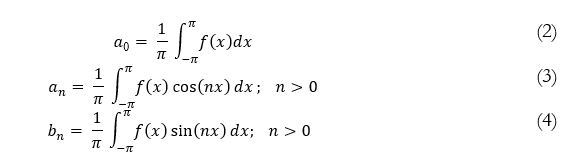
Where ao is the DC component, an is the even component, and bn is the odd component that can be computed by equations (2), (3), and (4), respectively [9].
By considering the square waveform that can be easily obtained by transistor-based inverters, one can know that it has a half-wave symmetry, so it will only contain odd components. Thus, the Fourier series will become:
|
(5) |
THD (total harmonic distortion) is a standard to measure harmonics in a particular wave. As for square waves, the harmonic distortion is found to be about 48.3%, and it is formulated by equation (6) and equation (6’) [5].
|
(6) |
|
(6’) |
Another way to describe the degree of distortion of a wave is the crest factor. As for square waves, the crest factor is found to be less than 1.41, and it is formulated by equation (7) [5].
(7)
The equations (6), (6’), and (7) can also be represented in terms of current values.
A more effective way to find out the harmonic content in a current wave is the total demand distortion (TDD) factor, which can be given by equation (8) [9].
(8)
Where, of phase ‘a’ can be found by:
(9)
Thus,
(10)
Or,
(10’)
Lower order harmonics are more severe and difficult to eliminate. The triplen harmonics cause the neutral conductor to overheat [5]. The intermingling between the positive and negative arrangement of harmonics in an electrical framework produces torsional motions in the motor shaft. These motions can be cataclysmic if the frequency reverberates with the normal mechanical frequency of the motor shaft itself.
In [10], the harmonic elimination method through modulation technique is proposed. Other methods to eliminate harmonics through the selective harmonic scheme are described in [11]–[13]. A prominent method to mitigate the harmonics is by using the various types of multilevel converters (MLCs), including the neutral point clamped converter (NPC) and modular multilevel converters (M2Cs) [14]–[17]. These power electronics-based converters are used in various emerging areas of power systems like wind farms, Solar PV Parks, HVDC transmission lines, electric vehicles connected to the grid, etcetera [18]–[23]. A detailed review was made in [24], [25], showing different types of filtering techniques like passive power filters, immunity level mitigation, active power filters, virtual impedance control method, multilevel converters, and integrated mitigation including their advanced forms [26].
This paper presents the behavior of the non-linear electric loads and studies the harmonic content and the mitigation of harmonic content through filtering techniques. To achieve that mitigation, two different techniques are presented in which a conventional scheme as well as an advanced algorithmic scheme are made. The latter one involves the calculation of all frequency content of a periodic wave. Then, by utilizing the fundamental frequency of the composite signal, all harmonics are replicated and subtracted from the composite signal to filter out these harmonics. The simulations performed in the MATLAB-Simulink® environment have shown that this approach reduces the THD significantly from the advanced electrical systems within the statutory limit of IEEE 519-2014 standard [27].
METHODS
Basic inverter types and analysis of harmonics
In this technological century, there is a drastic increase in demand of advance power electronic systems [28]. An approach developed in this paper is to rectify an AC wave into a constant level DC waveform and then invert that DC waveform into an AC waveform by using either the 2 or 3 level converter technique or the Sinusoidal Pulse Width Modulation (SPWM) technique (just like in UPS frameworks). Thus, the proposed analysis covers harmonic contents both at the generating end and the consuming end.
The Square Wave Inverter
It is a simple technique of triggering power transistors alternately every 600 for 1800 intervals. Figure 1 shows the output of the square wave inverter and its Fast Fourier Transform (FFT) analysis. The sample is taken for initial 5 cycles for a 50 Hz system, and THD% along with the frequency spectrum is obtained.
Figure 1. Output and FFT analysis of 3-level inverter.
The result shows although a comparative low THD content (29.26%) is on the lower side of the frequency spectrum, it is difficult to filter out that content from the described inverter.
The Sinusoidal Pulse Width Modulation (SPWM) based Inverter
This technique involves modulation of a triangular carrier wave (Ac) with a sinusoidal reference wave (Ar) of the desired frequency, which produces gate pulses for MOSFETS/IGBTS, as shown in Figure 2.
Figure 2. Modulation technique for SPWM pulses.
Figure 3 shows the output of the SPWM inverter and its Fast Fourier Transform (FFT) analysis. The sample is taken for the initial first cycle for a 50 Hz system, and THD% along with the frequency spectrum is obtained.
Figure 3. Output and FFT analysis of SPWM inverter.
Although the THD content of the SPWM inverter is high (50.69%), as shown in Figure 3, it is still on the high-frequency side and can easily be filtered out by using a high pass filter. Nonetheless, filtering of high-frequency harmonics is easy than that of lower ones, and most of them are also filtered out by the leakage reactance of the system’s transformers.
Filtering Techniques and Mitigation of Harmonics
With the introduction of harmonics in power systems, associated waveforms take complex shapes, and their characteristics differ from the perfect sinusoids. Fourier analysis requires a greater amount of computation, and decomposition of the waveforms into their basic components is difficult. However, several electronic processors have been developed for computations that give real-time analysis along with graphical plotting [29], [30].
Approach of Passive Harmonic Filters (PHFs)
The Passive harmonic filters (PHFs) include the series or parallel association of a regulated LC and RC circuit to frame a low impedance way for a particular harmonic frequency. The filter is connected in parallel or series with nonlinear loads to redirect the regulated frequency harmonic current far from the power supply. Low Pass RLC filter is simulated as shown in Figure 4:
Figure 4. RLC low pass filter.
Note that whereas Figure 1 shows the simulation of the square wave inverter without a filter, Figure 5 shows its filtered output along with the FFT analysis.
Figure 5. Output and FFT analysis of filtered waveform of a square wave inverter.
Taking the value of R at random 160 ohms and C = 20 μF for a 50 Hz system [5]:
|
(11)
|
For the value of inductance, it is calculated by the following equation:
|
(12) |
Then L becomes 500 mH for 50 Hz and C = 20 μF.
Although this Passive RLC filtering technique is cheap, easy to design, reliable, and highly efficient, the major drawback is that it causes resonance problems that can be adverse in some cases. It is also tuned for fixed frequency and provides set reactive power compensation. To compensate for all these drawbacks, the usage of an Adaptive Active Power Filtering technique for suppression of harmonics can be used.
Approach of Active Power Harmonic Filters (APHFs)
The output of the square wave inverter is initially filtered to make it a perfect 3-phase sine wave, and the non-linear load is driven from it. Furthermore, it is observed that from a non-linear load, the current is distorted, and to mitigate this distortion Active Power Harmonic (Adaptive) Filter (APHF) is developed.
Three-phase active power filters compensate currents in high power applications such as adjustable speed drives (ASDs). There are two kinds of active filters, one to compensate current (Current Source Active Filter-CSAF) and the other to compensate voltage (Voltage Source Active Filter-VSAF). VSAF is easy to implement in terms of controlling circuitry, and expenses like Shunt Active Power Filter (SAPF) is used to achieve the desired task (as shown in Figure 6). This SAPF uses the ‘P-Q, Instantaneous Power Theory,’ i.e., initially to convert the 3-phase into two axes components. Then by calculating the active and reactive powers, the relevant harmonics are filtered out by generating compensating currents [9], [31]–[33].
Figure 6. The active power harmonic filter (APHF).
The figure shows a possible parallel connection of the APHF or AHF, with a source inverter and a nonlinear load. By switching the three-phase switch, the filter can be connected to the system to filter unwanted harmonics.
RESULTS
Simulations are done with a 3-phase, 270 volts (RMS), 50 Hz supply (shown in Figure 7), and the non-linear load is operated by it.
Figure 7. 3-phase, the line-to-line voltages.
When a non-linear load was driven by it, the current waveform gets distorted and is displayed in Figure 8.
Figure 8. The distorted current waveform.
The nonlinear load distorted the current waveform, whereas the related FFT analysis is shown in Figure 9.
Figure 9. FFT analysis of the distorted current waveform.
The frequency spectrum having a THD of 30.32% shows a gradual decrease in harmonic content; hence a high pass filter can be used to mitigate them.
For continuously changing loads, a Shunt Active Harmonic Filter is connected across the transmission line, and the compensation currents produced are marked in Figure 10.
Figure 10. 3-phase active harmonic filter (compensation) current.
These compensation currents, when added to the distorted load currents, produce currents nearer to the fundamental sinusoidal currents, having only the fundamental frequency component. The filtered output current is displayed in Figure 11.
Figure 11. The filtered output current.
The figure shows a very close approximation of the filtered currents that produce lower harmonic contents and thus lower associated drawbacks. Two sub-types of the AHF method/technique are the FFT-based control and the Full Spectrum Cancellation control. In the first sub-technique, each harmonic amplitude and phase angle are calculated and then injected by the filter with an equal and opposite current to cancel out the particular harmonic current. In the second sub-technique, the controller of the filter removes the fundamental current component and cancels out the remaining harmonic spectrum [34].
The related FFT analysis is delineated in Figure 12.
Figure 12. FFT analysis of filtered current.
The frequency spectrum has a THD of 4.56%, shows a drastic decrease in the harmonic content; hence an active power filter is a good choice to mitigate harmonics in a distorted current waveform produced by nonlinear loads.
DISCUSSION
The PHF technique includes sub-techniques of series-connected inductors, parallel-connected tuned LC filters, and AC to DC multi-pulse converters. These sub-techniques can mitigate the harmonics by either offering high series impedance paths in the flow of harmonic currents or by offering tuned low-impedance grounded paths to the undesirable harmonics. The tuned filters require a higher level of system analysis to avoid capacitor failures and resonance problems. On the other hand, the multi-pulse converters do not require any rigorous system analyses.
Although the source plus line reactance can decrease the flow of harmonic currents while dealing with non-linear loads, mitigation can still be done by inserting extra series-line reactors. These reactors have a harmonic mitigation performance based on the load current. The tuned harmonic filters can ground the high-frequency harmonics by means of series or parallel connected tuned LC components. Although they can be used with the non-linear loads, they cannot decrease the content of all harmonics but do the elimination on an individual harmonic basis, as shown by the obtained simulation results. The mitigation of harmonics at their generation points is the best strategy to decrease the power losses associated with the harmonics. Otherwise, the farther the connection points of the filters in the power network, the more power losses will be occurred due to the presence of the system component resistances. The multi-pulse converters like six, twelve, eighteen, and twenty-four pulses can offer low frequency-based odd harmonics. The higher-order harmonics are present at a lower level. These multi-pulse converters can decrease the AC supply current harmonics and are used as either an uncontrolled rectifier or a controlled rectifier. These converters can also contain coupling transformers and smoothing inductors to improve the current waveform quality. The overall costs are acceptable when comparing with the associated costs of the non-filtering cases [33].
Also, the AHF technique can be used with the non-linear loads. It can mitigate the harmonics by injecting an equal but opposite current into the system to cancel out the undesirable harmonic contents. The size and cost of the AHF filter depend upon the magnitude of the filtering current. Another classification of AHF can be done on the connection type, which is series or parallel connected filters. The series-connected AHF produces more power losses and uses the SPWM voltage waveform to mitigate the voltage distortion.
On the other hand, the parallel AHF is connected with the power network and can mitigate the current harmonics besides a lower power loss. The AHF has the ability to switch mode converter but contains more cost. A solution is to make hybrid harmonic filtering (HHF) technique in which both PHF and AHF features can be merged, having variable harmonic mitigation with lower cost [35],[36].
Hence, after analyzing the obtained simulation results, the following facts can be observed noticeably:
- An AC generator's output voltage and current are nearer to a pure sinusoidal wave shape, thus producing no or very little harmonics. The associated drawbacks are also very minimal.
- The output voltage and current waveforms of an inverter (either used in a UPS or VFD) have a lot of harmonics and thus increased associated drawbacks.
- Whenever a linear load (having no electronic components) is connected with a pure sinusoidal generating source (like a synchronous generator), it produces negligible harmonics and doesn’t distort the current waveforms.
- Whenever a nonlinear load (having electronic components) is connected with a pure sinusoidal generating source (like a synchronous generator), it produces harmonics and distorts the current waveforms.
- Whenever a nonlinear load (having electronic components) is connected with a non-pure sinusoidal generating source (like an inverter), it produces harmonics and distorts the current waveforms up to a larger extent.
- For constant-nonlinear loads and sources, passive power filters, including shunt, hybrid, and series filters, are a good choice to mitigate the harmonics and associated drawbacks.
- For varying-nonlinear loads and sources, active power filters are an excellent choice to mitigate the harmonics and associated drawbacks.
- Besides these, the simulation-based analysis clearly provides the significance of the use of passive and active power filters for the mitigation of harmonics. However, the passive power filtering technique reduces the THD content from 29.26% to 1.45% but is not suitable for the variable nonlinear loads. On the other hand, it is evident that the active power filtering technique contributes a great deal to reduce the THD content of line currents associated with such loads. From Figure 9 and Figure 12, THD content is considerably reduced from 30.32% to 4.56%, so it satisfies the IEEE 519-2014 standard.
The results related with the two major filtering techniques are summarized in Table 1.
Table 1. Harmonics generation and mitigation analysis.
|
Type of Converter |
Case/THD% |
|
|
3-level square wave converter source |
No filtering applied/29.26% |
Passive harmonic filtering/1.45% |
|
PWM converter source |
No filtering applied/50.69% |
Passive harmonic filtering/0% |
|
Converter supply with non-linear load |
No filtering applied/30.32% |
Active power harmonic filtering/4.56% |
The system characteristics of the three major filtering techniques are summarized in Table 2.
Table 2. Comparisons of major filtering techniques.
|
Harmonic Technique |
Cost |
Harmonic Content |
Failure Rate |
Maintenance and Repair |
|
PHF |
Low |
Low but non-adaptive mitigation |
High |
High |
|
AHF |
High |
Low with adaptive mitigation |
Low |
Low |
|
HHF |
Medium |
Low with adaptive mitigation |
Medium |
Medium |
CONCLUSION
Electronic loads like semiconductor lights, computers, laptops, cell phones, uninterrupted power supplies, switched-mode power supplies, variable frequency drives, etc., show a non-linear trend in their impedances when they are in operation that causes harmonic generation. These harmonics have shown adverse effects on electrical systems, i.e., they distort the voltage and current waveforms of the consumer as well as the supply side. These effects include lowering of the: losses, poorness in total power factors, overheating of auxiliary power equipment, overloading of power factor correcting capacitors, production of electromagnetic interference (EMI), production of high neutral currents, random tripping of circuit breakers, damage to the equipment insulations, lesser energy unit cost, derating of equipment kVA ratings, etc.
This paper clearly shows the behaviors of various power sources and loads in producing harmonics and associated disadvantages. Also, it presents two prominent techniques to mitigate the harmonics in advanced power electronics systems. The conventional way of filtering, i.e., through the passive power filtering technique, is easy and cheap to implement but is not a permanent solution due to continuous load variation. The adaptive active power filtering techniques based on p-q theory contribute greatly to the mitigation of harmonics and solve the problem that arises due to load variation in passive filters. In addition, it meets the IEEE 519-2014 standard.
REFERENCES
[1] A. Kalair, N. Abas, A. R. Kalair, Z. Saleem, and N. Khan, “Review of harmonic analysis, modeling and mitigation techniques,” Renew. Sustain. Energy Rev., vol. 78, pp. 1152–1187, Oct. 2017, doi: 10.1016/J.RSER.2017.04.121.
[2] A. Alduraibi, J. Yaghoobi, and F. Zare, “Impacts of Grid Voltage Harmonics Amplitude and Phase Angle Values on Power Converters in Distribution Networks,” IEEE Access, vol. 9, pp. 92017–92029, 2021, doi: 10.1109/ACCESS.2021.3093026.
[3] D. Kumar and F. Zare, “Harmonic Analysis of Grid Connected Power Electronic Systems in Low Voltage Distribution Networks,” IEEE J. Emerg. Sel. Top. Power Electron., vol. 4, no. 1, pp. 70–79, 2016, doi: 10.1109/JESTPE.2015.2454537.
[4] S. Md. Munir and Y. W. Li, “Residential distribution system harmonic compensation using PV interfacing inverter,” IEEE Trans. Smart Grid, vol. 4, no. 2, pp. 816–827, 2013, doi: 10.1109/TSG.2013.2238262.
[5] T. Wildi, “Electrical machines, drives, and power systems - RMIT University Library,” p. 934, 2007, Accessed: Jun. 21, 2022. [Online]. Available: http://primo-direct-apac.hosted.exlibrisgroup.com/primo_library/libweb/action/display.do?tabs=requestTab&ct=display&fn=search&doc=RMIT_ALMA2148418760001341&indx=1&recIds=RMIT_ALMA2148418760001341&recIdxs=0&elementId=0&renderMode=poppedOut&displayMode=full.
[6] M. Rashid, A. Raheem, R. Shakoor, Z. A. Arfeen, and N. Husain, “SCADA Based Differential Protection of Power Transformers,” IMTIC 2021 - 6th Int. Multi-Topic ICT Conf. AI Meets IoT Towar. Next Gener. Digit. Transform., 2021, doi: 10.1109/IMTIC53841.2021.9719781.
[7] M. N. Malik, A. I. Toor, M. A. Siddiqui, N. Husain, and A. Nadeem, “Load flow analysis of an eht network using ETAP,” J. Multidiscip. Eng. Sci. Technol., vol. 3, no. March, pp. 4979–4984, 2016.
[8] “Rashid, Power Electronics: Devices, Circuits, and Applications, International Edition, 4/e, 4th Edition | Pearson.” https://www.pearson.com/uk/educators/higher-education-educators/program/Rashid-Power-Electronics-Devices-Circuits-and-Applications-International-Edition-4-e-4th-Edition/PGM1045578.html (accessed Jun. 21, 2022).
[9] P. S. Sanjan et al., “Enhancement of power quality in domestic loads using harmonic filters,” IEEE Access, vol. 8, pp. 197730–197744, 2020, doi: 10.1109/ACCESS.2020.3034734.
[10] A. Moeini, S. Wang, B. Zhang, and L. Yang, “A Hybrid Phase Shift-Pulsewidth Modulation and Asymmetric Selective Harmonic Current Mitigation-Pulsewidth Modulation Technique to Reduce Harmonics and Inductance of Single-Phase Grid-Tied Cascaded Multilevel Converters,” IEEE Trans. Ind. Electron., vol. 67, no. 12, pp. 10388–10398, Dec. 2020, doi: 10.1109/TIE.2019.2959499.
[11] K. Zhou, Y. Yang, F. Blaabjerg, and D. Wang, “Optimal selective harmonic control for power harmonics mitigation,” IEEE Trans. Ind. Electron., vol. 62, no. 2, pp. 1220–1230, Feb. 2015, doi: 10.1109/TIE.2014.2336629.
[12] F. J. González, A. Marquez, J. I. Leon, S. Vazquez, L. G. Franquelo, and J. Yin, “Flexible harmonic control for three-level selective harmonic modulation using the exchange market algorithm,” Proc. IECON 2018 - 44th Annu. Conf. IEEE Ind. Electron. Soc., pp. 5297–5302, Dec. 2018, doi: 10.1109/IECON.2018.8591231.
[13] M. Sharifzadeh, H. Vahedi, R. Portillo, L. G. Franquelo, and K. Al-Haddad, “Selective Harmonic Mitigation Based Self-Elimination of Triplen Harmonics for Single-Phase Five-Level Inverters,” IEEE Trans. Power Electron., vol. 34, no. 1, pp. 86–96, 2018, doi: 10.1109/TPEL.2018.2812186.
[14] A. Yahya, S. M. U. Ali, and N. Husain, “applications,” no. May, 2015.
[15] A. Moeini, S. Wang, B. Zhang, and L. Yang, “A Hybrid Phase Shift-Pulsewidth Modulation and Asymmetric Selective Harmonic Current Mitigation-Pulsewidth Modulation Technique to Reduce Harmonics and Inductance of Single-Phase Grid-Tied Cascaded Multilevel Converters,” IEEE Trans. Ind. Electron., vol. 67, no. 12, pp. 10388–10398, 2020, doi: 10.1109/TIE.2019.2959499.
[16] A. Yahya, T. Waqar, N. Husain, and S. M. U. Ali, “Hybrid Multilevel Topology Based High Power Quality Inverter,” no. October, 2015.
[17] S. Debnath, J. Qin, B. Bahrani, M. Saeedifard, and P. Barbosa, “Operation, control, and applications of the modular multilevel converter: A review,” IEEE Trans. Power Electron., vol. 30, no. 1, pp. 37–53, 2015, doi: 10.1109/TPEL.2014.2309937.
[18] N. Husain and S. M. U. Ali, “On integration of wind power into existing grids via modular multilevel converter based HVDC systems,” Int. J. Renew. Energy Res., vol. 10, no. 3, pp. 1060–1070, 2020.
[19] G. Muhay Ud Din, N. Husain, A. Yahya, and Z. A. Arfeen, “Mathematical analysis of advanced high voltage direct current transmission systems,” ICAEM 2021 - 2021 Int. Conf. Appl. Eng. Math. Proc., pp. 61–66, Aug. 2021, doi: 10.1109/ICAEM53552.2021.9547195.
[20] G. You, Z. Xu, S. Liu, L. Xiao, and N. Sheng, “Study on VSC-HVDC asynchronous interconnection schemes for regional grids with concentrated small hydropower,” Dianwang Jishu/Power Syst. Technol., vol. 40, no. 4, pp. 1059–1065, Apr. 2016, doi: 10.13335/J.1000-3673.PST.2016.04.012.
[21] S. F. Bin Shakil, N. Husain, M. D. Wasim, and S. Junaid, “Improving the voltage stability and performance of power networks using power electronics based FACTS controllers,” 2014 Int. Conf. Energy Syst. Policies, ICESP 2014, Dec. 2015, doi: 10.1109/ICESP.2014.7347014.
[22] Z. Arfeen et al., “Exposure of Electrically Driven Vehicles and Smart Vehicle-to-Grid Technology,” Int. J. Progress. Sci. Technol., vol. 30, no. 1, pp. 220–228, Dec. 2021, doi: 10.52155/ijpsat.v30.1.3859.
[23] Z. A. Arfeen et al., “Insights and trends of optimal voltage-frequency control DG-based inverter for autonomous microgrid: State-of-the-art review,” Int. Trans. Electr. Energy Syst., vol. 30, no. 10, p. e12555, Oct. 2020, doi: 10.1002/2050-7038.12555.
[24] X. Liang and C. Andalib-Bin-Karim, “Harmonics and Mitigation Techniques Through Advanced Control in Grid-Connected Renewable Energy Sources: A Review,” IEEE Trans. Ind. Appl., vol. 54, no. 4, pp. 3100–3111, Jul. 2018, doi: 10.1109/TIA.2018.2823680.
[25] S. T. Y. Alfalahi et al., “Supraharmonics in Power Grid: Identification, Standards, and Measurement Techniques,” IEEE Access, vol. 9, pp. 103677–103690, 2021, doi: 10.1109/ACCESS.2021.3099013.
[26] M. S. Bajwa et al., “Simulink Analysis and Mathematical Modeling of Parameters Variation for Thyristor based Speed Controller of Single Phase Induction Motor, Int. J. Innov. Sci. Technol.” vol. 3, pp. 45–58, 2021.
[27] R. A. Barr and V. J. Gosbell, “Power system harmonic voltage limits for the future,” Proc. Int. Conf. Harmon. Qual. Power, ICHQP, pp. 483–487, 2014, doi: 10.1109/ICHQP.2014.6842902.
[28] G. M. Ud Din, N. Husain, Z. A. Arfeen, A. Yahya, N. Iqbal, and F. Shaukat, “Emergence of Advanced Multi-Terminal HVDC Transmission Systems and DC Grids,” IMTIC 2021 - 6th Int. Multi-Topic ICT Conf. AI Meets IoT Towar. Next Gener. Digit. Transform., 2021, doi: 10.1109/IMTIC53841.2021.9719688.
[29] M. Y. Lada, I. Bugis, and M. H. N. Talib, “Simulation a shunt active power filter using MATLAB/Simulink,” PEOCO 2010 - 4th Int. Power Eng. Optim. Conf. Progr. Abstr., pp. 371–375, 2010, doi: 10.1109/PEOCO.2010.5559218.
[30] “Shunt Active Power Filter - File Exchange - MATLAB Central.” https://www.mathworks.com/matlabcentral/fileexchange/42627-shunt-active-power-filter (accessed Jun. 21, 2022).
[31] Y. Hoon, M. A. A. M. Zainuri, A. S. Al-Ogaili, A. N. Al-Masri, and J. Teh, “Active Power Filtering under Unbalanced and Distorted Grid Conditions Using Modular Fundamental Element Detection Technique,” IEEE Access, vol. 9, pp. 107502–107518, 2021, doi: 10.1109/ACCESS.2021.3101238.
[32] W. H. Ko and J. C. Gu, “Impact of Shunt Active Harmonic Filter on Harmonic Current Distortion of Voltage Source Inverter-Fed Drives,” IEEE Trans. Ind. Appl., vol. 52, no. 4, pp. 2816–2825, Jul. 2016, doi: 10.1109/TIA.2016.2552138.
[33] L. Motta and N. Faúndes, “Active / passive harmonic filters: Applications, challenges & trends,” Proc. Int. Conf. Harmon. Qual. Power, ICHQP, vol. 2016-December, pp. 657–662, Dec. 2016, doi: 10.1109/ICHQP.2016.7783319.
[34] H. A. Kazem, “Harmonic mitigation techniques applied to power distribution networks,” Adv. Power Electron., vol. 2013, 2013, doi: 10.1155/2013/591680.
[35] S. Khalid and A. Triapthi, “Comparison of Constant Source Instantaneous Power & Sinusoidal Current Control Strategy for Total Harmonic Reduction for Power Electronic Converters in High Frequency Aircraft System,” vol. 1, no. 5, pp. 314–322, 2012.
[36] A. K. Bashir. N, Narejo. S, Naz. B, Jawed. M. M, Talpur. S, “Non-invasive EEG based Feature Extraction framework for Major Depressive Disorder analysis,” Int. J. Innov. Sci. Technol., vol. 4, no. 1, pp. 110–122, 2022, [Online]. Available: https://journal.50sea.com/index.php/IJIST/article/view/179.
|
Copyright © by authors and 50Sea. This work is licensed under Creative Commons Attribution 4.0 International License. |