
Simulink Analysis and Mathematical Modeling of Parameters Variation for Thyristor based Speed Controller of Single Phase Induction Motor
Muhammad Shahzad Bajwa1, Muhammad Usman Keerio1, Noor Hussain Mugheri1, Rameez Akbar Talani1 , Rizwan Aziz Siddiqui1, Riaz Hussain Memon1
1Quaid-e-Awam University of Engineering, Science and Technology Nawabshah
* Correspondence: Muhammad Shahzad Bajwa , shahzadbajwa@quest.edu.pk
Citation | Bajwa. M. S, Keerio. M. U, Mugheri. N. H, Talani. R. A, Siddique. R. A and Memo. R. H, “Simulink Analysis and Mathematical Modeling of Parameters Variation for Thyristor based Speed Controller of Single Phase Induction Motor”. International Journal of Innovations in Science and Technology, Vol 3, Special Issue, pp: 45-58 , 2021.
Received | Dec 14, 2021; Revised | Dec 17, 2021 Accepted | Dec 19, 2021; Published | Dec 31, 2021.
Abstract.
The thyristor is a power electronics device that is widely used in various electrical appliances due to its lower on-conduction losses, easyavailability, lower switching loss, greater efficiency and cost-benefit. Mostly a thyristor is used in rectifiers and variable-speed drives. Almost 70% of loads used in the world consists of induction motors in various types and forms. In this work, a thyristor-based controller is used to control the speed of a single phase induction motor by adjusting the firing angle for the gate terminal of the thyristor. Depending upon the firing angle, the output voltage, output current, speed, power factor and the total harmonic distortion are varied which is analyzed through MATLAB/Simulink. Further curve fitting technique is used to formulate the mathematical relationships between varying parameters concerning thyristor’s firing angle. The findings of this work are helpful to achieve the best curve fit model for varying parameters concerningthe thyristor firing angle.
Keywords: AC-AC Voltage controller, Firing angle control, Capacitor start induction motor, Speed, Power factor, Total Harmonic Distortion.
- Introduction
Induction motors are used globally because of their simplicity, ruggedness and low cost, etc. Its applications varies from domestic scale i.e., refrigerators, washing machines, pumps, etc to the industrial scalei.e., electric vehicles, industrial robots, elevators and so on.
To improve the efficiency and performance of induction motors, speed control of the induction motor is required purposely to satisfy the load demand rather than to run with a constant speed [1].
The construction of a single-phase induction motor can’t self-start due to the absence of revolving magnetic flux. Therefore, an additional winding also known as the auxiliary winding is attached with the main winding to create an induction motor self-start. These two windings are displaced electrically at an angle of 90° and are attached in parallel arrangements across the main AC supply. The common types of single-phase induction motors are split-phase motors, Capacitor-start, Capacitor-start run motors, shaded pole motors, etc [2].
To manage the speed of the induction motor, a variety of methods are adopted such as changing the pole, adding rheostat in the stator, voltage control, voltage/frequency control, etc. Therefore, thespeed control of the induction motor is carried out by changing either the stator parameters such as the varying number of poles, supply voltage, supply frequency, etc, or rotor parameters such as varying external resistance attached with the rotor circuit, cascaded control, etc [3].
The conventional or traditional speed control methods experience various disadvantages including frequent maintenance, mechanical wear and tear, bulk and low efficiency. Consequently, the use of power electronic devices and controllers play a very important role in enhancing the mentioned disadvantages and also facilitate soft starting [4-7].
Depending upon the methodology, a range of techniques are applied for speed control. Recently a technique is used in the voltage control method for controlling the speed by connecting back to back anti-parallel thyristor pairs called AC voltage controllers with stator part of the induction motor. Different values of the thyristor’s firing angles generate different sequences of pulses that are applied to the gate of thyristors as shown in Figure1.

Figure 1. Input voltage, Output voltage, Thyristors pulses waveforms
By adjusting the value of the thyristor’s firing angle, the output voltage changes and that’s the reason behind thechange that occurs in speed since speed and voltage have a proportional relationship [8-9].
The benefits of using a thyristor-based controller include the smooth variation in the output voltage but the shape of the input sine wave is changed due to triggering of thyristor T1 and T2 and change of current due to inductive nature of load hence harmonics will be generated [10].
Due to switching in thyristors, harmonics will be generated. Harmonics are integral multiple frequencies containing a waveform which are added further with the fundamental frequency. If the fundamental frequency of a waveform is f, then its integral multiples will be 2f, 3f, 4f, 5f and so on.These integral multiples are said to be the harmonic frequencies or harmonic orders.
The study of the harmonics is necessary because they cause electromagnetic interference, poor power factors, heating and temperature rise of machines, decreasing lifetime duration and reducing the performance of the machine. Thus it is very important to identify dominant harmonic orders as well as total harmonic distortion (THD) in the system and to employ appropriate methods to mitigate the harmonic distortion [11-13].
Due to thyristor-based speed controller of single phase induction motor,this work not only enumerates the variation in other parameters but also establish the mathematical relationshipamong various parameters and thyristor’s firing angles.
- Material and Methods
Simulation Modeling
To show the effect of thyristor-based speed controller on various parameters of induction motor, a single phase capacitor start induction motor connected with the thyristor-based controller is modeled in MATLAB/Simulink as shown in Figure 2
The parameters used in Simulink modeling as shown in Table 1.
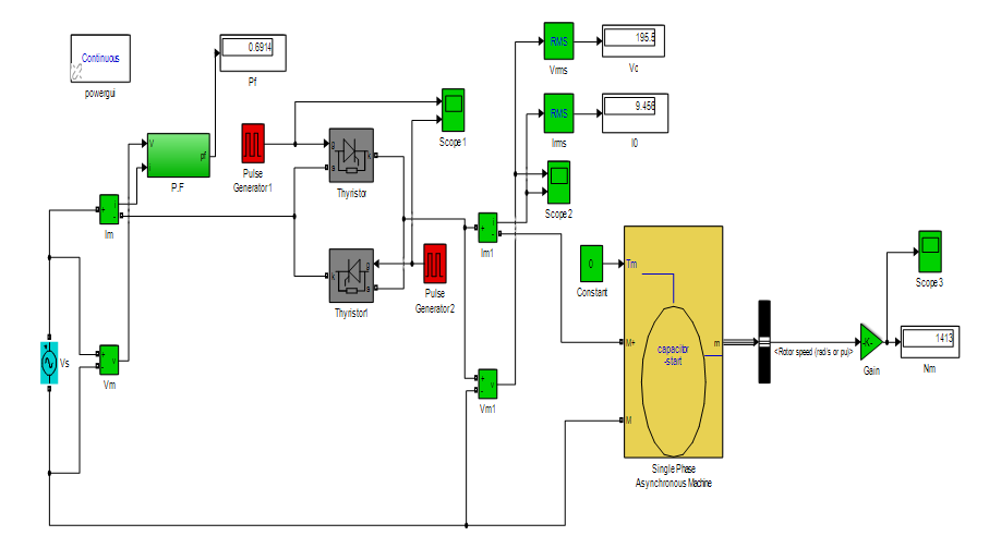
Figure 2. Simulink model of thyristor-based controller with capacitor-start induction motor
Table 1. Parameters used in simulink Model
|
Parametrs |
Values |
|
Input supply voltage(rms) Supply frequency |
220V 50Hz |
|
Power Rating |
0.25*746VA |
|
Thyristor’s firing angle |
0-1400 |
Result and discussion.
The Thyristor’s firing angle manages the voltage and hence the speed. The firing angle or the gate pulse for the gate terminal of anti-parallel thyristors were provided through pulse generator block in simulink which was like a simple pulse width modulation technique. Through triggering the thyristor T1 and thyristor T2, the output rms voltage was controlled. The pulsating sequence waveforms were given for 00 and 700 thyristor’s firing angles as shown in Figure 3. and Figure 4.
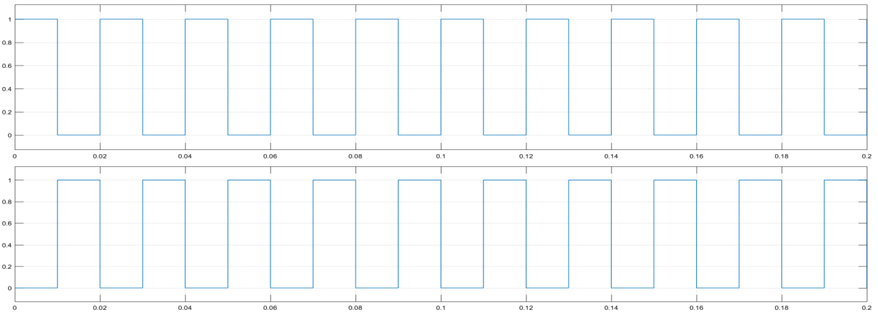
Figure 3. Gate pulses for T1& T2 at firing angle of 00
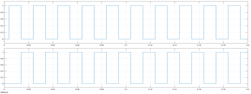
Figure 4. Gate pulses for T1& T2 at firing angle of 700
Similarly, gate pulses were generated for various thyristor’s firing angles. It is indicated in Figure 3. and Figure 4. that the sequence of gate pulses was moving in the right direction with increasing thyristor’s firing angles. These different pulses will chop or cut the sinusoidal supply voltages and this chopped form will be supplied to the statorcircuit. Hence by changing the thyristor’s firing angles increasingly give a falling speed.The results are shown below; Figure 5. and Figure 6. show the rotor speed at thyristor’s firing angle for 00 and 700.

Figure 5. Rotor speed at a firing angle of 00
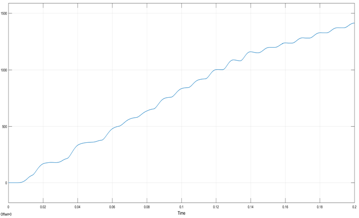
Figure 6. Rotor speed at a firing angle of 700
It can be seen that the speed of the induction motor comes to its steady-state level when time (t) is 0.18 seconds as shown in Figure 5.It was observed that by increasing the thyristor’s firing angle,the time required to reach steady-state speed was also increased as shown in Figure 6. for the firing angle of 700. Figure 7. and Figure 8. show the output voltage and current waveforms at thyristor’s firing angle for 00 and 700.

Figure 7. Output waveforms for voltage and current at a firing angle of 00

Figure 8. Output waveforms for voltage and current at a firing angle of 700
From the output current waveform, it is apparent from Figure 7 that at time t = 0.1 seconds the auxiliary winding gets disconnected and the induction motor only runs with the main winding current. Figure 8. Shows that as the thyristor’s firing angle increases the waveform distortion in voltage and current waveform distortion also increases. When the thyristor’s firing angle increases the %THD increases while the rms output voltage decreases.
The Fast Fourier Transform (FFT) of the output voltage and the output current are shown in Figure 9. and Figure 10. at a firing angle of 700.From the FFT analysis, the %THD in output voltage waveform was 19.45% and the %THD in output current waveform was 22.66%, while the 3rd, 5th and 7th harmonic orders were leading in nature. Hence the design of an appropriate filter was required to mitigate the leading harmonic orders and to reduce the %THD within the international standards limit.Table.2 provides the information regarding variation in parameters such as rms output voltage, current, motor speed, power factor, %THD of output voltage and current for different thyristor’s firing angles.
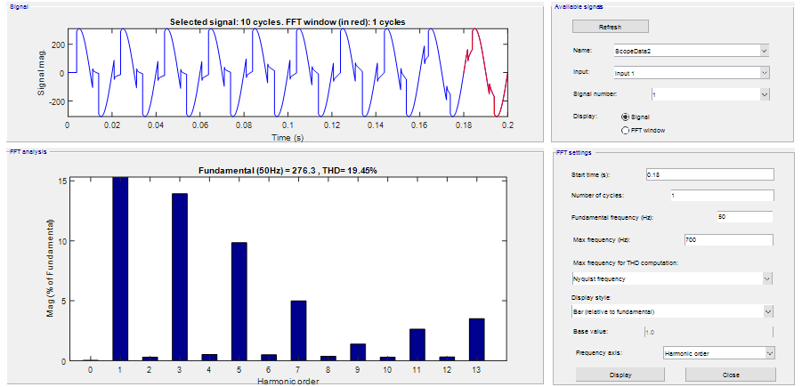
Figure 9. FFT analysis of output voltage at a firing angle of 700
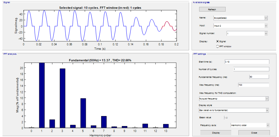
Figure 10. FFT analysis of output current at a firing angle of 700
Table 2. Result of variations in various parameters by changing thyristor’s firing angle
|
S.No |
Firing angle α (Degree) |
Output voltage (V) |
Output current (A) |
Motor speed Nm (RPM) |
Power factor Cosф |
THDv Output (%) |
THDi Output (%) |
|
1 2 3 4 5 6 7 8 |
00 200 400 600 800 1000 1200 1400 |
219.9 219.9 219.9 218.4 160 105.4 63.01 27.36 |
7.102 7.093 7.169 8.245 14.87 17.79 10.98 4.79 |
1503 1503 1501 1492 1236 706.5 246.9 47.11 |
0.15 0.16 0.18 0.46 0.63 0.58 0.40 0.22
|
0.28 0.25 0.29 3.22 47.17 84.92 122.06 189.95 |
0.32 0.25 0.29 4.69 47.17 84.92 72.20 100.01 |
|
|
|
|
|
|
|
Mathematical Modeling
It was observed from Table 2.that parameters such as output voltage, output current, speed, power factor, harmonic distortion vary by changing the thyristor’s firing angle. In this section, mathematical expressions of the lines that relate to the thyristor’s firing angle and different system parameters were derived using the curve fitting technique.
The goodness of the fitted line of the equation was determined by a parameter called residual or error. Residual is the difference between fitted function and the given data which is collectively known as Sum of Square due to Error (SSE). The value residual square (R-Square) should be 0.9 or 1 while the value of SSE should be zero or less than zero for the best curve fit [14].
- Output Voltage Variation
The obtained output voltage value variations were graphically drawn for thyristor’s firing angles from 00 to 1400 as shown in Figure.11. Goodness of fit: SSE: 7.176e-021 and R-square: 1

Figure 11. Firing angle Versus Output voltage
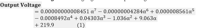
Goodness of fit: SSE: 7.176e-021 and R-square: 1
The significance of this method was that the output voltage can be calculated at any other thyristor’s firing angle. For example, if = 900 is taken, then by using equation 1, the predicted value of output voltage becomes 123.83v.
From the plotted curve, in Figure 11 it was observed that for 0°-60° range of firing angles, there was no drop in voltage, while voltage decreases rapidly after 700 of firingangle. After 1400 firing angle, there was a very low value of output voltage for which the speed is not feasible.
A. Output Current Variation

Figure 12. Firing angle Versus Output current
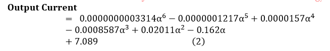
Goodness of fit: SSE: 0.4288 and R-square: 0.9969
In Figure 12. the output current value is constant like an output voltage for 0°-60° range of firing angle, while its value was increased for 70°-100° range of firing angle. After 1000 of firing angle the output current decreases.
A. Speed Variation
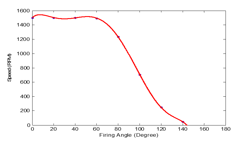
Figure 13. Firing angle Versus Speed
Goodness of fit: SSE: 2.959e-021 , R-square: 1
The graph of speed versus thyristor’s firing angle was shown in Figure 13. This graph is similar to output voltage versus thyristor’s firing angle graph because the value of speed fully depends upon the controlled value of output voltage. It was observed that the speed decreases in the same manner as output voltage variations.
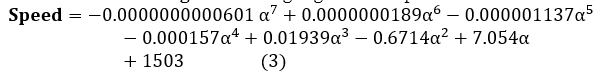
- Power factor Variation
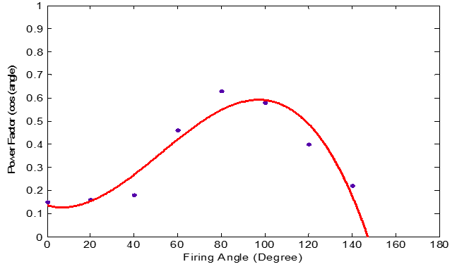
Figure 14. Firing angle versus power factor

Goodness of fit: SSE: 0.02594, R-square: 0.9031
In Figure 14 the relationship between the power factor and thyristor’s firing angle was graphically drawn. The value of the power factor increased for 0°-90° range of firing angle. While its value was again decreased after 90° of firing angle due to the power loss.
A. THDV Variation
Figure 15. Firing angle Versus THDv

A. THDi Variation
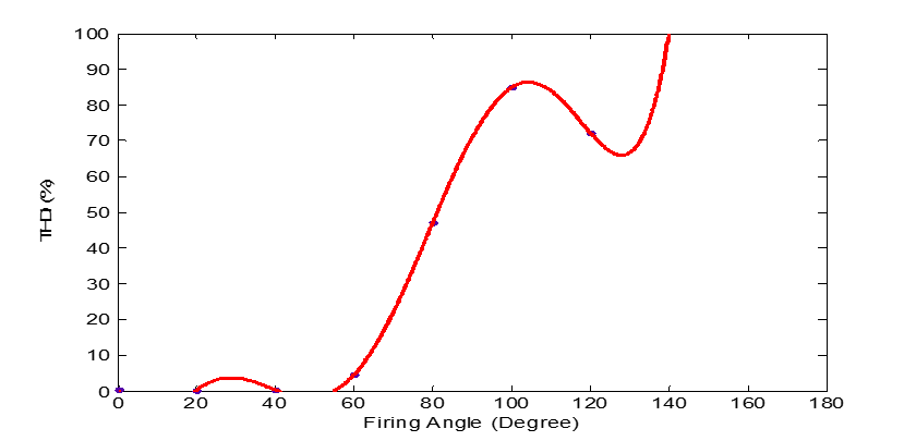
Figure.16. Firing angle Versus THDi
Goodness of fit: SSE: 2.323e-022 , R-square: 1
The %THDvand %THDi variations concerning the thyristor’s firing angles were graphically shown in Figure 15 and Figure 16. It became clear that both %THDV and %THDi were increasing with thyristor’s firing angle. The mathematical equations obtained from 1 to 6 using the curve fitting techniques can be used to calculate the mentioned parameter variations at any other thyristor’s firing angle.
Conclusion.
The paper analyzed the effect on system parameters due to thyristor-based speed controller of a single phase induction motor by varying the thyrister’s firing angle. It is observed that the parameters such as output voltage, output current, speed, power factor, harmonic distortion varies by changing the thyristor’s firing angle. Also mathematical expressions of the lines that relate to the thyristor’s firing angle and different system parameters were derived using the curve fitting technique. The scope of this work is that prior to use this system, it is necessary to identify precise and accurate phenomena of different varying parameters concerning to thyristor’s firing angle.
Acknowledgement. The first author would like to thank the Quaid-e-Awam University of Engineering, Science and Technology Nawabshah, Sindh for this research work and this work has not been published or submitted to other journals and all authors are agreed with the content of manuscript and this work will be published in this journal.
Author’s Contribution. Conceptualization, M.S.B and M.U.K.; Methodology, M.S.B..; Investigation, M.S.B.; writing—original draft preparation, M.S.B; writing—Review and editing, M.S.B, M.U.K, N.H.M, R.A.T, R.H.M ; Supervision, M.U.K.
Conflict of interest. The Authors declare no conflict of interest for publishing this manuscript in IJIST.
Project detail. Nil
REFRENCES
|
1. K.Sundareswaran,“An improved energy-saving scheme for capacitor-run induction motor,” IEEE Transactions on Industrial Electronics, vol. 48, no. 1, pp. 238-240, Feb. 2001. |
|
2. M. Dey, S. Nehal, and A. Imran,“Monitoring the Variation of Speed for Single Phase Induction Motor Using Antiparallel Back to Back Connected Silicon Controlled Rectifier,” In Proceeding 3rd International Conference on Mechanical Engineeering and Renewable Energy , pp. PI-279,2015. |
|
3. S. Rahman, and A.A. Abidin, “A Review on Induction Motor Speed Control Methods”, International Journal Of Core Engineering & Management vol.3, no.5, 2016. |
|
4. M. Jannati, S. A. Anbaran, S. H. Asgari, W. Y. Goh, A. Monadi, M. J. A. Aziz, and N. R. N. Idris,“A review on Variable Speed Control techniques for efficient control of Single-Phase Induction Motors: Evolution, classification, comparison,” Renewable and Sustainable Energy Reviews,Vol 75, pp.1306-1319,2017. |
|
5. M.A. Hannan, J. A. Ali, P.J. Ker, A. Mohamed, M.S. Lipu, and A. Hussain,“Switching techniques and intelligent controllers for induction motor drive: Issues and recommendations, ”. IEEE access, V.6, pp.47489-47510, 2018. |
|
6. H.C. Chuang and C.T. Lee, “The efficiency improvement of AC induction motor with constant frequency technology”, Energy, Vol.174, pp.805-813, 2019. |
|
7. M.A. Niazi, Q. Hayat, B. Khan, and M. Afaq, “Speed Control of Three Phase Induction Motor using Variable Frequency Derive Control System”. International Journal of Current Engineering and Technology, E-ISSN, pp.2277-4106, 2020. |
|
8. R. P. Akabari, and H. buch, “Modeling of split phase induction motor with single phase cycloconverter,” Journal of Information, Knowledge and Research in Electrical Engineering,” Vol.02, no.2, 2013. |
|
9. R. Gupta, R. Lamba, and S. Padhee, “Thyristor Based Speed Control Techniques of DC Motor: A Comparative Analysis”, International Journal of Scientific and Research Publications, Vol. 2, Issue 6, June 2012. |
|
10. M.A Mahar, M.A. Uqaili, and A.S Larik,“ Harmonic analysis of AC-DC topologies and their impacts on power system,” Mehran University of Engineering and technology, Vol.30, Jan, 2011. |
|
11. A. Altintas,"A Comparative Study on ac Voltage Controllers in Terms of Harmonic Effectiveness", Erciyes University Journal of Science and Technology, Vol. 21, No.1- 2, pp. 79-86, 2005. |
|
12. M. U. keerio, M. S. Bajwa , A. S, Saand, M. A. Memon, “Harmonic measurement in computer laboratory and design of passive harmonic filter using MATLAB ,” International Journal of Advanced Computer Science and Applications, Vol. 8, No.12, pp.1-9, 2017 |
|
13. M. S. Bajwa, M. U. keerio, N.H.Mugheri, M.A. Koondhar, I.A. Channa, “An Experimental Analysis of Harmonic Distortion Indices In Home Based Electrical Appliances and Improvement Using Passive Filter ” Quaid-E-Awam University Research Journal of Engineering, Science & Technology, Nawabshah , Vol.19, |
|
14. M. S. Bajwa, A. P. Memon, J. A. Ansari, and M. T. Bhatti,“An Experimental Investigation Based on Mathematical And Software Modeling of Total Harmonic Distortion in Personal Computer ” , Bahria university journel of information and communication Technologies Vol.9 ,Issue 1 , pp.62-73, 2016. |