
Sun Tracking and Control Design for PV Solar Energy System
Sheher Bano1, Syed Irtiza Ali Shah1, Adeel Ahmed Abro1, Umbreen Tariq1
1Air University, Islamabad.
* Correspondence: Adeel Ahmed Abro, ahmedadeel8271@gmail.com
Citation |Bano. S, Shah. A. I, Abro. A. A, Tariq. U, “Sun Tracking and Control Design for PV Solar Energy System,” Int. J. Innov. Sci. Technol., vol. 4, Special Issue, pp.77-93 , 2022
Received | June 6, 2022; Revised | June 20, 2022; Accepted | June 28, 2022; Published | June 30, 2022.
______________________________________________________________________________________________________________________________
In this modern era of the rapid increase in population, a high rise in technology, and a large number of machinery installed, fuel demand has increased significantly. Non-renewable energies contribute a lot to producing energy worldwide, and that's why they are decreasing at an alarming rate. As an alternative, renewable energies have a high potential to solve this upcoming issue. In this paper, sunlight is utilized for the location of Islamabad, and an active solar tracker is designed. The objective is to develop a cost-effective system with low maintenance requirements. The tracking mechanism is modeled by two sensors, LDR and PV sensor. LDR sensor generates high resistance when light is incident on them, thus reducing the voltage production. PV sensors produce a voltage when sunlight is incident on them, and a voltage drop occurs if a shadow occurs. A thin plate between two LDR sensors or two PV sensors will cast a shadow according to the sun's position. It will create a voltage difference between the two sides, thus causing the system to track the sun. For smooth movement, a servomotor is an effective choice. The system is integrated with a microcontroller for a feedback system of output; Arduino Uno will regulate the uniform and accurate movement of the system. The research on azimuth and elevation angles for the location of an installment is also included in this paper. Different tests are performed for comparative study for both sensors to have performance analysis.
Keywords: Renewable Energy; Solar Energy; Tracking mechanism; LDR and Solar panels; Arduino UNO
Introduction
Over the past few decades, the world has had a major energy crisis. The situation is more intense in third-world countries because of a severe difference between energy production and demand. With this ever-increasing demand, the non-renewable resources of energy seem not to be sufficient enough. To meet the energy requirement, many researchers suggested that renewable sources might be the alternative to the major energy resources of today.
Renewable resources are of different kinds, including Solar, Wind, Hydro, Geothermal, Biomass, etc. Solar energy is one of them the most eco-friendly mean of energy production. If we consider the phenomenon of absorption and diffraction, the total flux reaching earth is 1 the 08*10^8 GW and the total energy is 3,400,000 EJ annually. This value is nearly seven to eight thousand times of energy requirement. If this energy is used effectively and productively solar energy has the potential to solve the current issues of energy crisis.
Solar Cells
A solar panel is a combination of photovoltaic cells along with protective glass and a frame of plastic or metal. The most effective types of solar cells are Monocrystalline, Poly _crystalline, and amorphous because of their overall performance and wide applicability. A study conducted shows that monocrystalline has better energy production than the amorphous type, following can be depicted in the Figure.1 too in a graphical manner: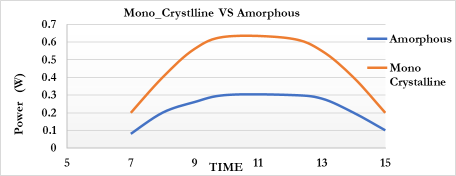 Figure 1. Power generation comparison of Monocrystalline vs Amorphous type [1]
Another study conducted shows that monocrystalline works more efficiently with poly-crystalline types of solar cells when there is no drastic change in average solar radiations. This shows cell type of solar cell that can be used among these three for uniform solar flux is mono-crystalline. Figure. 2 shows the comparison between monocrystalline and polycrystalline cells.
Solar Tracking
The efficiency of a solar panel that is fixed on a frame lies in the range of 15-25% only. On the contrary, the solar panel accompanied by solar trackers can have an efficiency of about 32-40% [2]. Now for the solar tracking systems, we have two types:
Single Axis Tracking
This system follows only one trajectory, which is majorly from East to West. The single-axis tracking can have an efficiency of about 27- 32%. There are different types of single-axis solar trackers, one with single axis tracking in a horizontal plane or tracking with an inclined panel to increase efficiency, other is single axis tracking in the perpendicular plane with either flat or inclined panels.
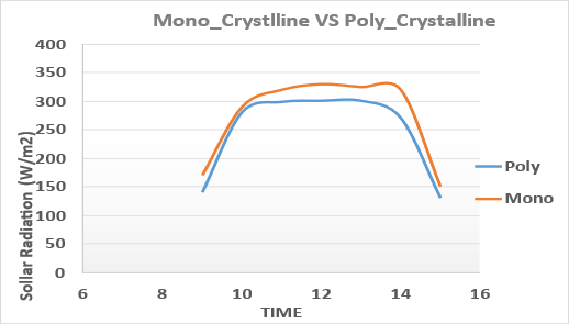 |
Figure 2. Hourly measured solar radiation by Monocrystalline vs Polycrystalline solar cells [1]
|
Dual Axis Solar Tracking
Even though a single axis tracker system increases the efficiency of solar cells, we still have the potential to increase the efficiency even more. The sun changes its path season-wise, Figure. 4, so if a solar panel can track this changing trajectory too along with east to west motion, its efficiency can increase. A dual-axis solar tracker is used for this purpose. A dual axis system can increase the efficiency of the solar tracker to about 35-40% [3].
Solar Tracking via Micro-Controller
A solar tracker system incorporated micro-controller can have high performance and efficiency. Micro-Controller can be of two types: Close and open, the weather gets feedback from the sensor that the solar panel has reached the microcontroller or not. The opened-type microcontroller doesn't have such a feedback mechanism.
|
|
Figure 4. Proposed conceptual control system for solar track |
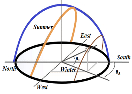 Figure 3. Proposed trajectories change for generic variation in sun path through summer and winter [4]
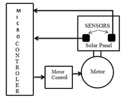
This paper aims to increase the performance of solar panels by tracking the sun. Solar panels have to be designed to follow the sun. In this paper, the tracking mechanism is performed by two different options. Firstly, through LDRs to align the system with the sun, secondly through solar panels as the sensor.
A microcontroller is installed with the system to regulate the voltage and get the desired result accurately. A comparison is drawn at the end between both means. The scope is to devise a cost-effective sign with less maintenance and simple configuration. This is because of all the complexities added to the system to increase it and s performance and reduce the life span of solar panels. So, the goal is to design an effective system with a simple design. The system designed is an indigenous control system with a new sensor and actuation mechanisms m. Moreover, this is solely based on previous research. Also, this control system is implementable on physical solar panel assemblies.
Material and Methods.
A dual-axis solar tracker system is designed. For simplicity, the elevation angle is controlled manually while the azimuth angle is tracked by rotating the system. It is achieved by converting the fixed frame into a rotating one with the aid of a servomotor. The system will rotate freely to become aligned to the sun via a sensing mechanism.
This sensing mechanism is firstly drawn from two LDR systems placed left and right of the system. The Light Dependent Resistor (LDR) will sense and track the sun thus moving the system accordingly. Between the LDRs, there is a thin plate placed. If the sun position is not right at the top, it will cast a shadow on either of the LDRs, thus adjusting the system. Best performance is possible when the intensity of sun rays is the same on both LDRs.
For the next model, instead of LDRs, two PV sensors of 10V are used. Between these PV sensors, a thin plate is placed. It will cast a shadow on either of them; according to the sun's position. The shadow will reduce the intensity of sun rays, thus reducing the voltage production, this voltage difference will align the system to the sun. Using solar panels will provide a comparative study for efficiency and performance.
The microcontroller used in this paper is Arduino UNO. Arduino is known best for its simplicity, flexibility, and ease of utilization. However, Arduino has an upper limitation on voltage, 5V. To integrate the second system; with the differential PV sensor, a buck converter is used to reduce the 10 V to 5V.
Calculation of Solar Panel Angle
Solar panel orientation to the sun is of major concern. The angle of the solar panel for the sun depends upon the area in which the solar panel is installed. To maximize the absorption of solar energy solar panels should directly face the sun. To gain maximum solar energy solar panels should be vertical during winter and more tilted during summer.
Since the sun is always in motion so its azimuth and elevation angle are changing continuously. The prime location of our concern is Islamabad having longitude and latitude of 33.6844° N, 73.0479° E. To determine azimuth and elevation angle, Sun Rise, and Sunset designed two models utilizing both of these sensors, side by side, to have comparative results and to judge the performance.
Novelty Statement
Many research work is available on tracking solar systems using LDR as a sensor, using two or four LDRs. Similarly, many differential PV sensors are also available. In this study, we have designed two models utilizing both of these sensors, side by side, to have comparative results and to judge the performance.
The first model that was developed is sun tracking with an LDR sensor that operates via Micro-Servomotor. In this model, LDR sensors are used as a sensing element with a divider between two LDR. The divider serves the purpose of shading elements on the sensor. When the sun is moving towards the East there is a shade on LDR that is on the west side, as a result, it gives the digital value of “0” while the other gives the value of “1”.Our system is programmed in such a way that the LDR sensor gives the digital value of “1” until both LDR has a digital value of “1”.The servomotor motor stops when both LDR has either value of “1” or “0”.This model was developed to understand the basis of Sun Tracking.
Table 1. Monthly change for azimuth angle/elevation angle[5]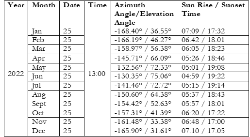 Material and Methods
Solar Tracking System with LDR expressed in Figure 5
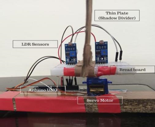 Figure 5. Proposed system setup with LDR Sensor
Components
Arduino UNO
Microcontrollers are small computers capable of doing simple tasks with efficiency. These small circuit boards are so designed that they can be powered by a small battery. And they can be powered for days using small cells.
Microcontrollers are integrated circuits. These circuits use logic provided in their programming to do simple tasks. Arduino is a company based in Italy that is responsible for making circuits that make the usage of microcontroller IC easy and time-saving These boards are called Arduino. Another positive factor about Arduino is that they are open source. Hence, they are used in a wide variety of market products [6].
The Arduino is programmed using special software in which the loops are applied. These loops define the path of the Arduino working. These loops are then implemented in the microcontroller and then actuate the system accordingly. The circuit can be just a simple circuit or multiple circuits can be operated using a single Arduino.
Furthermore, Arduino is capable of reading data from sensors that are presented as INPUTS. In a complete system sensors and actuators are coupled up to make a complete circuit and complete a task.
Hardware
There are many different Arduino boards available, but only the Arduino UNO will be examined. The Arduino UNO is a microcontroller board based on the ATmega328, an Atmel 8-bit AVR RISC-based microcontroller with high performance. The device runs on a voltage range of 1.8 to 5.5 volts.
The component of Arduino are as follows:
Table 2.Description of Arduino components [7]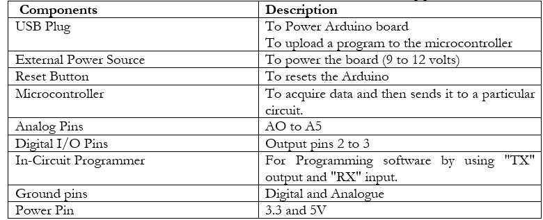 Software
The Arduino ecosystem is free and simple to use. It is written in Java and is based on free source tools such as Processing. It has a code editor with various features and also the sort out and submit programs to the board. A "sketch" is a program developed for Arduino by using C or C++ language [6].
The Arduino IDE (integrated development environment) Figure 6 incorporates a software library and has a command area, text area, and message window area. The Arduino IDE is available for Windows as well as MAC and Linux. This makes it the easiest to use almost and most accessible software for Arduino programming [7].
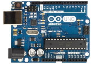 |
Figure 6. The picture was taken on the white background of Arduino Uno Rev 3 used as a controller
|
Servo Motor
A servo motor is an actuator (rotary or linear) that is capable of controlling position (angular or linear), velocity, and acceleration precisely. It comprises a motor that accompanies a position feedback sensor.
"Servo motor" refers to a particular type of actuator (linear or rotary). It is a servo mechanism, which indicates that the motor's motion is continuously observed and controlled [8].
Working
A servo motor presented in figure 7, is an electromechanical device that employs voltage and current to generate velocity and torque. A servo motor is utilized in closed-loop control, to provide velocity and torque as directed by a servo controller, which closes the loop via a feedback device. This device then sends data to the controller as a result of commanded parameters motor movement is modified. The control cable is used to provide a variable width electrical pulse or pulse width modulation (PWM) to the servos. A rotation of 18degreesee (90 degrees in either direction) is possible using a motor. The motor stop when at a point where the potential of rotation is equal for both direction (clockwise and counterclockwise). The rotor turns into the desired position with the help of PWM provided to the motor, which is depending on the duration of the pulse sent over the control line [8].
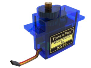 |
Figure 7. The picture was taken on the white background of Servomotor SG90 used for actuation
|
Light Dependent Resistor (LDR)
The LDR Module s shown in Figure 8, is a sensor-based module that can be coupled up with the Arduino. The LDR module mainly consists of an LDR sensor which is further attached to a circuit. The LDR module works on a very simple principle. When light is incident on the LDR module, the electrical resistance drops. Consequently, the voltage increases.
This voltage can be fed into the Arduino Microcontroller both digitally and analogically. Digitally the output would be 1 when light hits the sensor and 0 when it is not incident
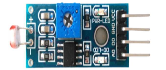 |
Figure 8. The picture was taken on the white background of LDR Module LM 393 used for light sensing |
Bread Board
A bread Board is a base for constructing electronic circuits and electronic prototyping. The breadboard has certain sets of connections already made on it. This allows easy testing and prototyping of electronics. Moreover, using a breadboard does not require any kind of soldering. All the soldering and connection processes are already done.
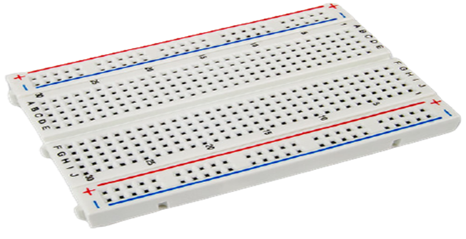 |
Figure 9. The picture was taken on the white background of Bread Board used for the implementation of circuit
|
Flow Diagram of System
Figure. 10 shows the algorithm the system will follow;
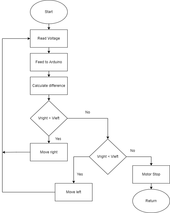 Figure 10. Proposed flow diagram of solar tracking system with LDRs Sensor
Sun Tracking with Differential PV sensor
 Figure 11. A picture was taken of the lab mockup based on differential PV sensors
The Second model that was developed is comparable to the original system on which the controller needs to be operated. In this system, solar panels serve the purpose of sensing elements with a divider (voltage divider) in between[9]. The motor driver control the direction of rotation i.e., clockwise (towards east) anticlockwise (towards west), and Speed.
The power to drive the system is taken from a 12 V dc motor. The divider serves as a shading element. When the sun is moving toward the east the solar panel on the east side gets a voltage of 5 V while the other panel on the west side due to shading ga etc a voltage less than 5V as a result of this system moving toward the east. The motor stops when either each sensor has a voltage less than 5V or the voltage of both sensors is 5V.
Components
Motor Driver
L298N Motor Driver Module is a high-performance motor driver used for Stepper and DC Motors. It is used for controlling the direction of rotation and also the speed the of DC motor. For this purpose, the following methods are used:
PWM: controlling speed.
- Bridge: controlling the direction of rotation.
PWM (Pulse Width Modulation)
PWM (pulse width modulation) is a method that is common for payload speed control by changing the DC motor’s voltage for managing speed. Input voltage average value is adjusted by transmitting on and off pulses. The average value of voltage depends upon the Duty cycle (proportional to the pulse’s width [10]).
H-Bridge
H Bridge is utilized to control spinning direction by changing DC’s motor polarity.
The motor's spinning direction changes when the voltage applied is reversed when both particular switches close [10].
Table 1: L298N Module Pinout Configuration[11]
|
Components |
Functions |
L298N Motor Driver IC |
Has a heat sink and can control two motorist or independently |
Power Supply |
Pitch Screw Convertor to power motor driver |
|
IN1 and IN2 |
Input pins for Motor A. Motor A's spinning direction are controlled by this device. |
|
IN3 and IN3 |
Input pins for Motor B. Motor B's spinning direction are controlled by this device. |
|
ENA |
PWM signal for Motor A is enabled. |
|
END |
PWM signal for Motor B is enabled. |
|
OUT1 and OUT2 |
For Motor A |
|
OUT3 and OUT4 |
For Motor B |
|
12V |
12V from a DC power supply |
|
5V |
Provides power to the L298N IC's switching logic circuits. |
|
GND |
Ground Pin |
Voltage Drop of L298N
The L298N motor driver encounters a 2V voltage drop which is due ta o voltage drop across H Bridge transistors. the motor is not able to get the desired amount of voltage. To cater to this problem motor should supply voltage higher than desired.
Buck Converter
A buck converter is a device that is used that is a Step-down voltage adjuster. It is a DC-to-DC converter that consists of switches, a transistor inductor-capacitor, and a diode. In a boost converter, the position of the transistor and inductor is switched. Normally, power electronics switches are used. The switch can be turned on and off with the aid of a PWM signal [12]

Make a Submission
We are Indexed Here


![]()


![]()
![]()


![]()
